CAD Output (Make AutoCAD Objects)
Icon:
![]()
![]()
Introduction
In order to improve drawing speed and automatic display updates as design changes are made, Advanced Road Design makes use of 'quick draw' functionality (proxy graphics) available in AutoCAD/BricsCAD. Most notably, surface display components (such as triangles and contours) and design plan linework utilises 'quick draw' technology for drawing representation.
By default, non Advanced Road Design users will not be able to view any of the 'quick draw' graphics.
This command exports the graphic results into the AutoCAD drawing as polylines and AutoCAD objects, for plotting and viewing by non Advanced Road Design users.
Note: Whilst Contour labels are displayed as AutoCAD text, their position is determined by the display of contours for the surface object. Until the CAD Output command is run, editing the surface or contour interval will result in the relocation of the contour labels.
Details
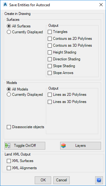
Upon selecting the command the following form is displayed:
 |
|
| Create in Drawing | This what data to output to the drawing, and whether to output 2D and/or 3D information. |
| Surfaces | Surface Output Controls |
| Radio Buttons Surface Selection | Output all surfaces into the drawing (All Surfaces), or only those set to display in the drawing (Currently Displayed) |
| Output | Tick on what to output:
|
| Models | Controls output of the plan drafting linework |
| Radio Buttons Model Selection | Output plan drafting linework for all Models (All Models) or only those set to display (Currently Displayed) |
| Output | Tick on what to output:
|
| Disassociate Objects | By default, each object created by the
software is identified as having come from this export via the inclusion
of extra data (xdata) on the object. This can cause problems when users want to
manually edit the object, because the software uses this data to identify
the object as coming from this output process and will delete and
replace the object based on the current model/s whenever this command is
run. Tick on Disassociate Objects to remove this association - objects are not deleted and replaced when this command is run, if this is ticked on during export. |
| Click to set the display status for
surfaces and/or models. Refer |
|
| Layers | This enables user control over the colours and layers for the different cross section Codes used for each String object. The opens the Assign Layers command. |
| LandXML Output | This exports out the
Surface and Alignment data into a LandXML file suitable to importing
into AutoCAD Civil 3D and other civil engineering design packages. Note: By default, separate XML files are output for the alignments and DTM's and are saved to the location of the Data folder, in a folder named XMLExchangeFiles. |
| XML Surfaces | Tick on to output the surfaces to a LandXML file |
| XML Alignments | Tick on to output the alignments to a LandXML file |
| OK | Apply and exit. |
| Cancel | Exit the form without deleting any data. |