CSD Layer List
Icon:
![]()
![]()
Menu: Roads > Settings > CSD Layer List
Ribbon: Roads Tab > Plan Production Panel > Assign Layers
Roads Tab > Settings Panel > CSD Layer List
Introduction
When a String is created, the software automatically plots the string and cross section codes as linework in the drawing. This form controls two aspects of the linework representation in the drawing:
-
Display on/off: For any Code in the list, the user can select whether or not the linework for that code is or isn't drawn for that Code
-
Layer Used: The layers assigned are automatically applied in the drawing based on the name of the Code/s associated with the String.
Users can get control over the layers used for:
-
The automatic linework display (the fastdraw linework)
-
The output of linework as 2D polylines (using the
 CAD Output command)
 -
The output of linework as 3D polylines (using the
 CAD Output command)
Special Note: It is assumed that all the layers being referenced in this form exist in the drawing - if a new drawing is created and the layers don't exist, the software will initially create them and assign colours from this form.
Users are required to set up all the Codes they have applied to their string designs - for each Code the user can assign layers to use in the display/output of the linework.
The form allows for multiple edits of cells. The process for applying multiple edits is:
-
Tick on the 'Multiple Edits' tick box for each layer that is to be edited
-
Click on one of the layer properties (colour or linetype) that is to be changed. Make a change. The change will apply to all layers ticked on for Multiple Edit
Note: The layer edits applied here are made for the current project only - use the Global CSD Layer List command to set layers, colours and linetypes to apply for all future projects.
Hierarchy for Layers
This form allows the assignment of layers and for LAYER OVERRIDES to the AutoCAD linework output. Here are the control options:
-
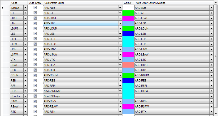
Auto Draw: This is the automatic linework displayed as the design is created and edited. The layer controls here completely define the layers used in the drawing. Designers pick layers from the drawing to use - they can also set an 'override' layer to be used instead of the default. Both layers must exist in the drawing.
-
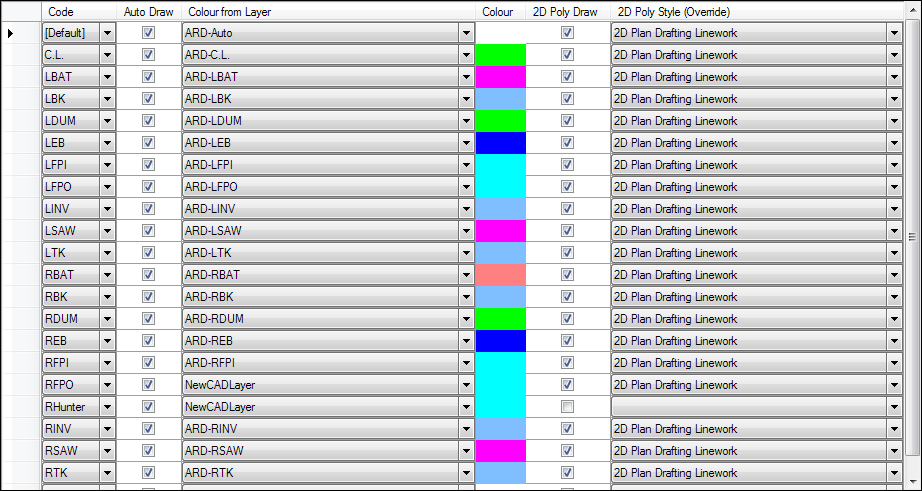
2D Polylines: The column for 2D Poly Style (Override) can be used to set a layer to apply for each Code when output to 2D Polylines. If this cell is BLANK (no input shown) then the layer will come from the
 Active Drawing Settings form > Layer Names tab > Explode
to 2D Polyline entry.
 -
3D Polylines: The column for 3D Poly Style (Override) can be used to set a layer to apply for each Code when output to 3D Polylines. If this cell is BLANK (no input shown) then the layer will come from the
 Active Drawing Settings form > Layer Names tab > Explode
to 3D Polyline entry.
Note: The [Default] entry at the top of the layer list will be applied to any and every Code not explicitly defined in the list.
Default Layer List
When any job is started, the layer list is created locally for editing.
The layer list comes from the CSD Settings folder - from the file RoadLayerDisplay.Disp. The best way to access this file is to:
-
use the Load Style button on this form to load the file
-
edit the layer list details
-
use the Save As button on this form and save/overwrite the RoadLayerDisplay.Disp.
Details
Upon selecting the command the following form is displayed:
|
|
|||||||||||||
| Add Code |
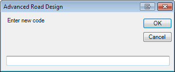
Click to add a new Code to the list. Inputs are as
follows:
|
||||||||||||
| Add Layer |
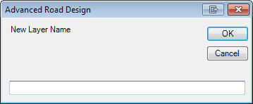
Click to add a new Layer in the drawing. Inputs are as
follows:
|
||||||||||||
| Layer Colour | Click to open the Select Colour form - select a colour and click OK to change the colour of this layer in the drawing. | ||||||||||||
| Layer Styles |
The Layer Styles accesses the exact same form as described
in the
|
||||||||||||
| Load/Save | Hover flyout commands to save the layer settings or recall layer settings saved | ||||||||||||
| Save As |
Save the layer settings as a Layer Style. This is (by
default) saved to the CSD Settings folder and can be
recalled at any time and applied to a drawing. In the form, type in a name and OK. Users can select a particular location for the settings file. |
||||||||||||
|
Load Style |
Save the layer settings as a Layer Style. In the form, select the file and OK. | ||||||||||||
|
Editing Linework Settings for |
Radio button options to control layer assignment for the
Auto draw linework, 2D polyline linework output and 3D
polyline linework. |
||||||||||||
| Auto |
This controls the auto draw linework (also known as fast
draw linework). Inputs as follows:
|
||||||||||||
| 2D |
This controls the 2D polyline linework layers when the
linework is exported to 2D polylines. 2D Polyline Inputs as follows:
|
||||||||||||
| 3D |
This controls the 3D polyline linework layers when the
linework is exported to 3D polylines. 3D Polyline Inputs as follows:
|
||||||||||||
|
OK |
Apply and exit. |
||||||||||||
|
Cancel |
Exit the form without applying layer changes. |
||||||||||||


