Edit 3D Face Mapping File
Icon: ![]()
Menu: Roads > Settings > Edit 3D Face Mapping File
Ribbon: Roads Tab > Modelling Panel Slideout > Edit 3D Face Mapping File
Introduction
Designers are able to output their design surface model as layer (and color) discriminated 3D faces via the
![]() Display Surface as 3D Faces command.
Display Surface as 3D Faces command.
In order to control what layers (and colors) are used for the different components of the design, a Mesh Definition File needs to be applied.
When the software is installed a default Mesh Definition File called MSHSTandard.txt is included.
This command simply opens the MSHStandard.txt file for editing.
Details
Upon selecting the command the following form displays:
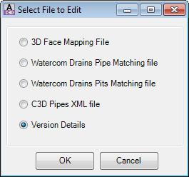
A form will open listing the 3D Face Mapping Files. Select the 3D Face Mapping File to edit and click OK.
A sample of the file is shown, below, including an explanation of the file format.
A Mesh Definition File is required for the
![]() Display Surface as 3D Faces command.
Display Surface as 3D Faces command.
About Mesh Definition Files - Layer and Color Control for 3D Faces
Designers create and use Mesh Definition Files to control which layers/colors are applied to different features of the road surface. 3D Faces are created between adjoining cross section labels/strings - the Mesh Definition File works by setting pairs (or triplets) of cross section labels and assigning the layer/color to use for the 3D faces created between these labels.
Mesh definition files are text file/s located in the 'common' directory - click here for more information on the storage location of the configuration files. For the software to recognise a Mesh Definition File it must be saved with MSH in the prefix of the name of the file (eg: MSHStandard.txt).
A mesh definition file is a comma delimited text file, with each line defining a set of cross section labels and a color (RGB) and layer to apply between the labels. The format of the file is as follows:
- Label 1, Label 2, Color Red #, Color Green #, Color Blue #, Layer Name Suffix, or
- Label 1, Label 2, Label 3, Color Red #, Color Green #, Color Blue #, Layer Name Suffix
Between a pair of labels (Label 1 - Label 2) the software will create 3D faces on a user defined layer (this is a combination of a Layer Name Prefix and the Layer Name Suffix typed in the file appended to it to make a Layer Name - click below for more information) and with the AutoCAD color specified (RGB).
Designers need to create as many lines as is required to accommodate each label pair that is likely to occur.
An example of a Mesh Definition File is shown below:
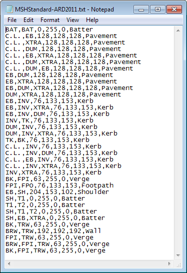 |
In the MSHStandard.txt example file, left:
Note: Ignore the L and R parts of the label name when forming the mesh definition file - the software will automatically accommodate the addition of the L and R prefixes to labels used for each road. When the software creates 3D faces with a label combination not covered in the Mesh Definition File the 3D faces are assigned to a unique layer with suffix '-Label1-Label2-Label3' and with colour set to Red. |
New mesh definition files can be created simply by copying the existing MSHStandard.txt using Windows Explorer or SaveAs file and renaming it MSH<Your Input>.txt.
Layer Names Applied in the Drawing
The actual layer name used in the drawing is a combination of the name referred in this file and the Layer Name Prefix read from the ![]() Active Drawing Settings - Layer Names tab.
Active Drawing Settings - Layer Names tab.
A display of the ![]() Active Drawing Settings - Layer Names is shown below, with the relevant Layer Name
Prefix highlighted:
Active Drawing Settings - Layer Names is shown below, with the relevant Layer Name
Prefix highlighted:
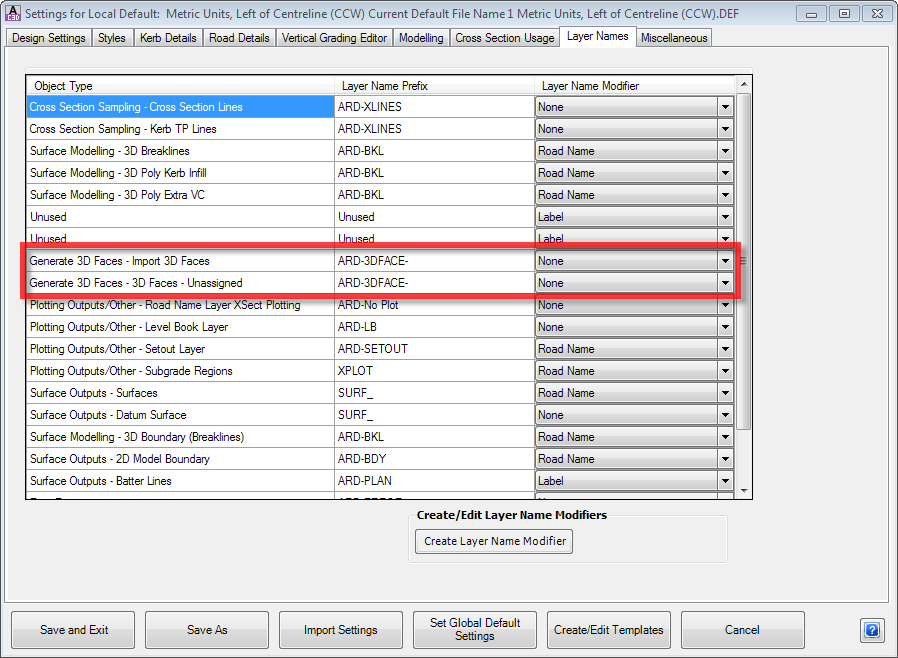
The Layer Name Prefix for Import 3D Faces and 3D Faces - Unassigned are used to create the Layer Names for the 3D faces, with the layer name in the MSHStandard.txt (or user edited MSH*.txt file) being appended to the Layer Prefix to form the Layer Name.
In the example above, combining both the information in the the Layer Prefix of the Active Drawing Settings and the MSHStandard.txt file for the 3D faces between the C.L and the EB would result in the following layer name being used in the drawing:
CSD-3DPavement
CSD-3D is read from the Layer Prefix in the Active Drawing Settings - Layer Names tab
Pavement is read from the MSHStandard.txt file.