Display Surface Model as 3D Faces
Icon: ![]()
Menu: Roads > Display Surface Model as 3D Faces
Ribbon: Roads Tab > Modelling Panel Slideout > Display Surface Model as 3D Faces
Introduction
Display Surface as 3D Faces enables the designer to create a surface of 3D faces that includes layer and colour control (between labels) for a road network.
With these commands the designer can quickly and easily create surface models with the road pavement, kerb and channel, footpath and naturestrip (and any other surface that can be defined between two (or three) labels on your road cross section) on different layers and with different colours.
Before starting this command:
- Ensure that the option Create Mesh for Imported Faces is ticked ON under the Modelling tab in the
 Active Drawing Settings
 - Create a Civil 3D surface from Civil Site Design (normally
 Auto Model command) - the software concurrently creates an alternate model enabling label assignments to the triangles for differential layering
 - Ensure that you have a Mesh Definition File containing the layer controls you would like applied to the outputted 3D faces - see the command option
 Edit 3D Face Mapping File to learn more about the format of the file and the controls
Special Note - RDV Customers: Users with the Rapid Design Visualisation (RDV) software can map the surface materials to the separate layers containing 3D faces to create a realistic, fully rendered 3D visualisation of the road network, including the ability to run animations (drive the roads) and add street furniture, trees, linemarking, buildings and other features.
The 3D Faces can also be readily exported to other visualisation packages such as 3ds Max.
Details
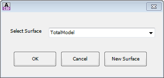
Upon selecting the command the following form is displayed:
 |
|
| Select Surface | Select the surface required. The surface must have been created using either Auto Model or Model Manager. |
| New Surface | Click to create a new surface. |
| OK | Apply and continue. |
| Cancel | Cancel the command. |
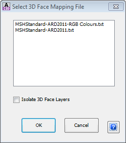
Once the surface has been selected the following form is displayed:
 |
|
| 3D Face Mapping File | The 3D Face Mapping File controls how colours and layers are applied to 3D faces that define the surface. In essence, the file simply identifies a pair or triplet of design cross section codes and sets the colour and layer name to apply to 3D faces that are created between the two (or three) codes. The MSHStandard.txt 3D Face Mapping File is included at the time of installation of the software and is opened directly from the |
| List | Select the 3D Face Mapping File to be used. |
| Isolate 3D Face Layers | Select this option to turn off all layers except for the layers of the 3D faces representing the surface selected. |
| OK | Apply and exit. |
| Cancel | Cancel the command. |
A sample output of the command is shown, below:
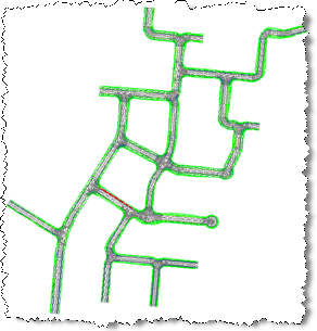 |
| A view of the surface model using the mesh definition file MSHStandard is shown, above.
The MSHStandard file sets out the colors and layers of 3D faces Note: Stray 3D faces may be created between the ends of the roads - designers can simply delete the unwanted 3D faces.
|
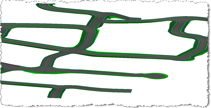 |
| Different parts of the road model are set on different colors and layers.
3D view here highlights how the layers are applied. |
Advanced Presentation
It is possible to map materials to both the 3D face layers and the surface layer and to obtain a material rendered visualisation in AutoCAD Civil 3D.
Most customers requiring visualisation are using RDV to generate 3D environments of the design inclusive of material mapping and option camera runs.
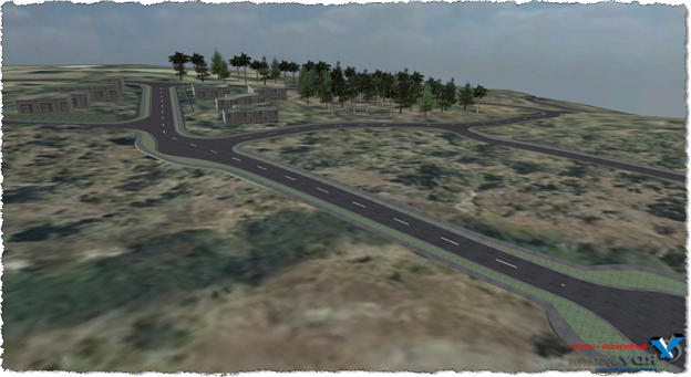 |
| This is an RDV output of the design, above. Users can move around in this output anywhere and can also run animations. All 3D geometry data is collected and included into the RDV scenes.
The file size is relatively small and anyone can view the outputs. For more information go to www.rdvsystems.com |