Compute & Apply Superelevation
Icon: ![]()
![]()
Introduction
This command is used to automatically apply superelevation to any Road String in accordance with local, state and country standards.
The major features of the superelevation command include:
- Ability to control the design parameters from which the superelevation is derived, so making adjustments to suit local conditions is easy;
- Analysis of every curve and automatic application of superelevation to suit;
- Full editing capabilities of individual entries and by adjusting the design parameters for each curve;
- Additional cross section sampling can be applied to pick up the feature points of the superelevation.
The superelevation is managed via a single form with two tabs:
- The Design Inputs tab defines the general design parameters, and;
- The Superelevation Results tab displays the applied superelevation values and enables editing of the superelevation applied to a Road.
Entries made in the form are used to make adjustments to the crossfalls and widths of the edge of roadway (and optionally a 'shoulder' code left and right).
The superelevation applied makes adjustments to the finished surface templates - designers can use the Variation tools and other adjustments to further adjust the cross sections.
(It is also possible to simply use the template merge options and the Variation tools to achieve the required superelevation. The choice of tools is up to the designer - largely depending on the type and length of the road. It is also possible to simply use the superelevation computed by Civil 3D for the alignment).
Superelevation - Alignment Constraints
The software calculates crossfall adjustments along the tangents (optionally with a percentage inside the curves) between curves. In order for this to occur the software is expecting the alignment to include:
- A tangent section (it can be quite short) at the start of the alignment;
- Tangents between every curve (can be short);
- A tangent section (can be short) at the end of the alignment.
If these requirements are not met then the software will generate an error message and abort the superelevation process.
Superelevation - General Process
The process for applying superelevation is as follows:
- Set the design parameters via the Design Inputs tab;
- Press the Compute Superelevation button;
- Review, amend and adjust the crossfall adjustments via the Superelevation Results tab and by direct editing in the cells;
- Click OK to exit the form and apply the superelevation. This also re-extracts the cross sections, taking into account the additional Chainage (Station)s at superelevation points;
- Use Variations as desired to further edit any superelevated Code/s.
The superelevation applied to the Road is dependent on the content of the (country dependent) Superelevation Table - refer to the heading Superelevation Tables - Output Control for further information.
Details
Upon selecting the command the user is prompted to select an alignment. After selecting an alignment, the following form is displayed:
| File Menu | |||||||||||||||||||||||||||||||||||||||||||||||||||||||||||||||||||||
| File > Export to Excel | Create an Excel (.xls) file with the superelevation results | ||||||||||||||||||||||||||||||||||||||||||||||||||||||||||||||||||||
| File > Import from Excel | Import and exported Excel file. Formatting must match in order to be imported. | ||||||||||||||||||||||||||||||||||||||||||||||||||||||||||||||||||||
| Design Inputs Tab | The Design Inputs tab defines the general design parameters to be used for creating the superelevation. | ||||||||||||||||||||||||||||||||||||||||||||||||||||||||||||||||||||
|
|||||||||||||||||||||||||||||||||||||||||||||||||||||||||||||||||||||
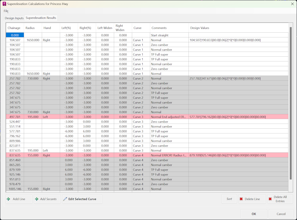
| Superelevation Results | The Superelevation Results tab is used to review and edit the Superelevation applied using the design parameters. The cells for each curve is coloured to help identification. Any design compliance warnings will highlight the row red. | ||||||||||||||||||||||||||||||||||||||||||||||||||||||||||||||||||||
|
|||||||||||||||||||||||||||||||||||||||||||||||||||||||||||||||||||||
| OK | Saves the current applied superelevation (as set in the Superelevation Results tab) and exits the form. | ||||||||||||||||||||||||||||||||||||||||||||||||||||||||||||||||||||
| Cancel | Exits the form without saving changes made since opening the form. | ||||||||||||||||||||||||||||||||||||||||||||||||||||||||||||||||||||


Superelevation Tables - Output Control
Superelevation tables are used to determine the superelevation lengths and cross falls to apply to each Curve.
Preliminary design tables have been provided for the following Countries:
- Australia
- ARD-AustRoads-Speed.txt file - DO NOT DELETE THIS DEFAULT FILE
- ARD-AustRoads2010-Desirable.txt - desirable minimum superelevation lengths
- ARD-AustRoads2010-Absolute.txt - absolute minimum superelevation lengths
- India (Internal to the software - no file selection required)
- U.S.A. ARD-Imperial-Speed.txt - based on AASHTO settings
- South Africa ARD-SA-Superelevation.txt - based on metric AASHTO settings
Note: It remains the Designer's responsibility to review these tables to ensure that they meet the local, state and/or country standards.
Special Note: The superelevation files must be stored in the 'common' directory and have a name with prefix ARD (eg: ARD-Superefile.txt) and extension .txt to be included in the list of available superelevation files.
Superelevation applied to a Road (excepting India) is made based on a superelevation table:

Shown, above, is part of the Superelevation Table created for Australian road design conditions (ref: Austroads Rural Road Design, 2003 - absolute minimum standards). The format of the table (comma delimited text file) is as follows:
- Requested Super (%), Speed
- This is followed by a series of lines setting out the superelevation to be applied depending on the radius of the curve:
- Radius, Maximum Superelevation to Apply, Superelevation Length (1 lane), Superelevation Length (2 lanes), Superelevation Length (3 lanes)
Each Superelvation/Speed combination is separated by a line containing an asterix (*).
Shoulder Rotation Files
The format of a Shoulder Rotation file is shown, below:
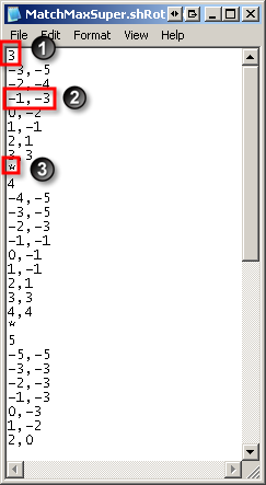
It contains a number of sections which define the relationship between the pavement crossfall and the shoulder crossfall for a range of maximum crossfalls.
1. The first line in the section specifies the maximum crossfall being applied to the roadway.
2. Subsequent lines specify the actual road crossfall and the required crossfall for the shoulder code/s. Values of the shoulder crossfall are interpolated from this table. These 2 values MUST be separated by a comma (,).
It is assumed that the values in the table are increasing by the road crossfall and are in sequence.
3. An asterisk (*) indicates the end of a section.