Alignment Offset Labels
| Menu: | Via Label Plan |
| Ribbon: | Via Label Plan |
Introduction
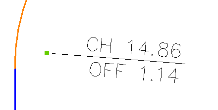
Chainage/Offset (Station/Offset) Labels will produce a variety of intelligent labels using an alignment and (optionally) surface. This type of label allows random insertion of points at user defined locations and can display alignment information such as offset and chainage. You can additionally report surface elevation information.
The user can produce a series of label styles in the drawing each with its own predefined style. The styles created can be used for other projects and stored within the global settings for inclusion in new projects. Label Styles are managed via the Label Styles command for Surface Elevations (the Alignment and Surface Elevation labels are in the same group).
When an alignment label is inserted the direction of the label is, by default, oriented perpendicular to the alignment (direction from the alignment centreline positive moving away from the alignment in both directions). If the label contains lines with changes in the positive X direction, then the line will be drawn perpendicular to the alignment and in a direction away from the alignment. Text set to zero rotation will display perpendicular to the alignment.
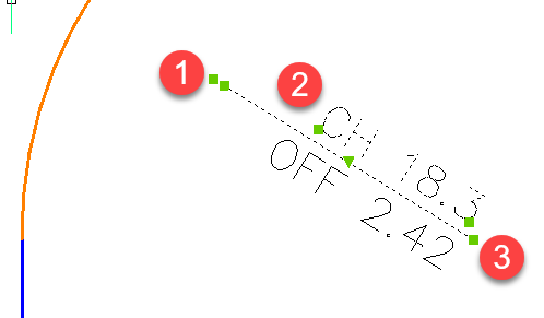
Label styles allow for text and lines to be rotated and moved independently in the drawing (it is usual to add a Symbol (block) to act as the Marker. The Marker is the object to move to change the insertion position of the label). Text can also be associated to a line created in the label style.
| Grip Editing | ||
|
 |
|
|
Moving the marker grip will reposition the entire label and update the Label content if referencing an alignment (and/or surface). Use the Sychronise Labels command to update label contents where necessary. |
|
|
Moving the text grips will reposition the Label text only. |
|
| Users can grip edit any lines added to the Label Style. After any grip edit of the line, the direction is set (does not change angle when moved around). Only the Reset Labels option can reset this back to being dynamic to the alignment direction. | ||
Updating Labels |
||
| Labels values will update using the following methods: | ||
|
||
|
||
|
||
|
||
About Label Groups and Alignments
When a Label Group is created, the user is prompted to select an ALIGNMENT to associate to labels created in that group. A new Label Group should be created for EACH alignment for which chainage(station)/offset labels are required.
Details
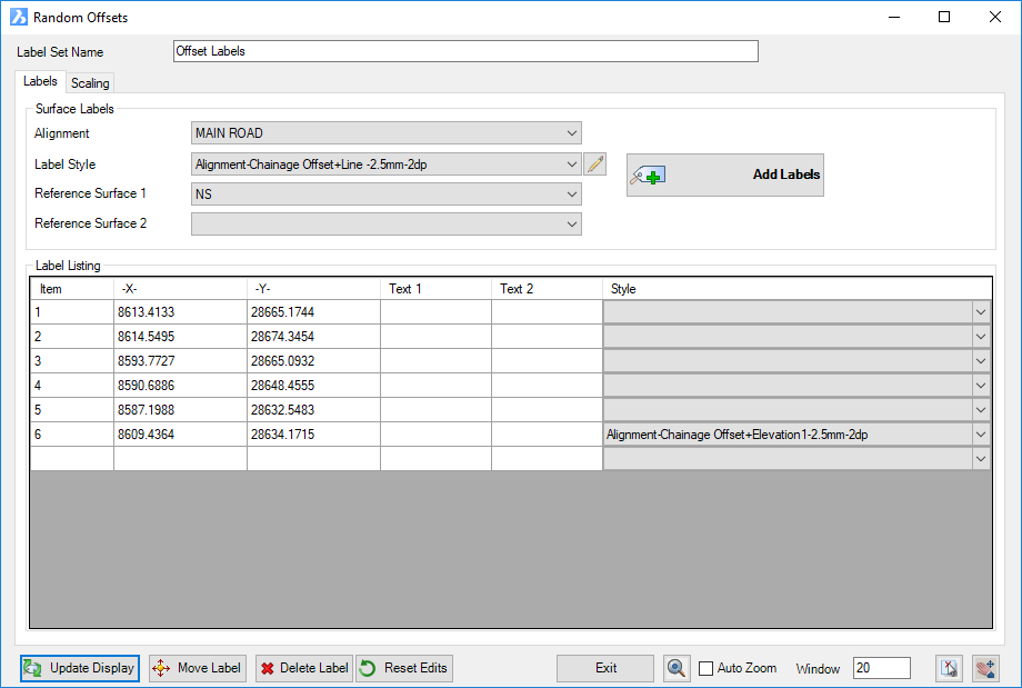
These are created via the Label Plan command. If new, users will need to firstly name the group. The followng form displays:
|
|||||||||||||||||||||
Label Set Name |
Name of the currently selected label set (not editable). |
||||||||||||||||||||
|
Delete the current Label Set Name with option to delete all associated label objects in drawing |
||||||||||||||||||||
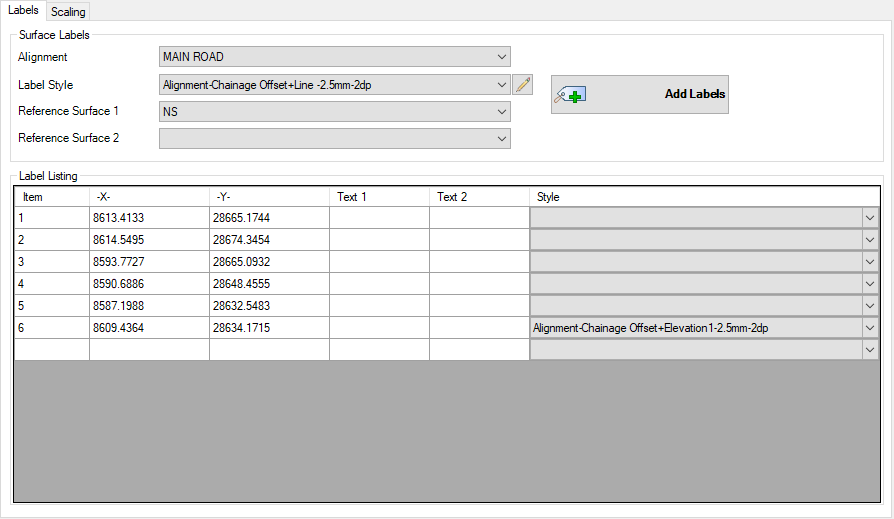
Labels Tab |
This tab manages the parameters for the labels |
||||||||||||||||||||
|
|
||||||||||||||||||||
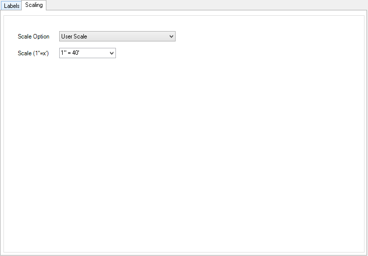
Scaling Tab |
This tab manages the scaling of the labels within the drawing |
||||||||||||||||||||
|
|
||||||||||||||||||||
Output / Editing |
These functions enable the user to edit & refine the labels in the drawing |
||||||||||||||||||||
|
Select to update the display of all labels in the drawing |
||||||||||||||||||||
|
Select a label from the list to move within drawing. User will be prompted to pick a new label position on screen |
||||||||||||||||||||
|
Select a single label from the list and delete from the drawing |
||||||||||||||||||||
| Select to reset grip edited labels to default positions. This will also restore any Labels that have been accidentally erased from the drawing. | |||||||||||||||||||||
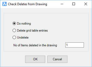
| Check Deletes | Select to manage labels that have been
deleted using AutoCAD Delete in the drawing. These
are listed in the list of labels and are highlighted with a coloured
background. They can be restored or permanently deleted
from the label list. Upon selecting the button the following form will display:
|
||||||||||||||||||||
| Exit the 2 Point Slope Labels command | |||||||||||||||||||||
| Click to zoom the drawing to the label highlighted in the label list | |||||||||||||||||||||
| Ticking this box will zoom the screen to a selected label in the list | |||||||||||||||||||||
| Click to select a label in the drawing and highlight it for edit in the label list | |||||||||||||||||||||
| Pan in the drawing. Press [Enter] or [Esc] or mouse button to return to this form. | |||||||||||||||||||||