Surface 2 Point Slope Labels
| Menu: | Via Label Plan |
| Ribbon: | Via Label Plan |
Introduction
Surface 2 Point Slope Labels will produce a variety of intelligent labels directly onto a surface. The tool is designed to allow the user to randomly place customisable labels over a surface manually, and optionally use a secondary surface to demonstrate elevation differences.
The user can produce a series of label styles in the drawing each with its own predefined style. The styles created can be used for other projects and stored within the global settings for inclusion in new projects. Label Styles are managed via the Label Styles command for 2 Point Slope Labels.
| Grip Editing |
 |
Moving the marker grip will reposition the entire label and update the Label content if referencing a surface. Use the Sychronise Labels command to update label contents where necessary. |
Moving the text grips will reposition the Label text only. |
| Users can create a Label Style which will generate leaders from the marker to the Label text if the text grip is dragged a specified distance. |
Updating Labels |
||
| Labels values will update using the following methods: | ||
|
||
Details
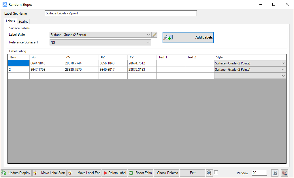
These are created via the Label Plan command. If new, users will need to firstly name the group. The followng form displays:
|
|||||||||||||||||
Label Set Name |
Name of the currently selected label set (not editable). |
||||||||||||||||
|
Delete the current Label Set Name with option to delete all associated label objects in drawing |
||||||||||||||||
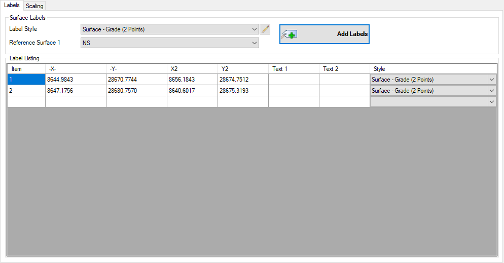
Labels Tab |
This tab manages the parameters for the labels |
||||||||||||||||
|
|
||||||||||||||||
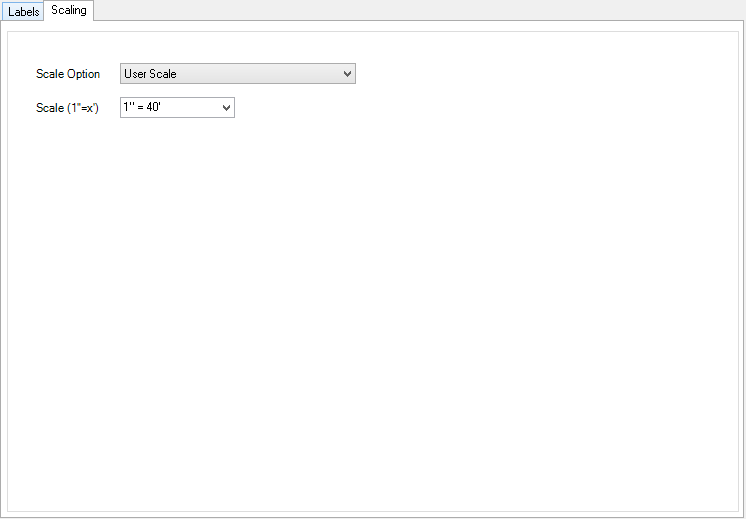
Scaling Tab |
This tab manages the scaling of the labels within the drawing |
||||||||||||||||
|
|
||||||||||||||||
Output / Editing |
These functions enable the user to edit & refine the labels in the drawing |
||||||||||||||||
 |
|||||||||||||||||
|
Select to update the display of all labels in the drawing |
||||||||||||||||
|
Select a label from the list to move within drawing. User will be prompted to pick a new label position on screen. This moves the Start point of the line component of the label. |
||||||||||||||||
|
Select a label from the list to move within drawing. User will be prompted to pick a new label position on screen. This moves the End point of the line component of the label. |
||||||||||||||||
|
Select a single label from the list and delete from the drawing |
||||||||||||||||
| Select to reset grip edited labels to default positions. This will also restore any Labels that have been accidentally erased from the drawing. | |||||||||||||||||
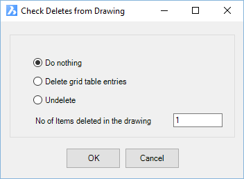
| Check Deletes | Select to manage labels that have been
deleted using AutoCAD Delete in the drawing. These
are listed in the list of labels and are highlighted with a coloured
background. They can be restored or permanently deleted
from the label list. Upon selecting the button the following form will display:
|
||||||||||||||||
| Exit the 2 Point Slope Labels command | |||||||||||||||||
| Click to zoom the drawing to the label highlighted in the label list | |||||||||||||||||
| Ticking this box will zoom the screen to a selected label in the list | |||||||||||||||||
| Click to select a label in the drawing and highlight it for edit in the label list | |||||||||||||||||
| Pan in the drawing. Press [Enter] or [Esc] or mouse button to return to this form. | |||||||||||||||||