Use this command to create and update surfaces created from a variety of data sources. Normally this command will be used to create existing surface
data for extraction of levels to use in a design, however it can be used to construct a surface from any assortment of 3D data.
The surface is managed in the drawing as an object (when selected, the AutoCAD Properties dialogue identifies it as an AutoCAD Point object) - selecting the object and
right clicking will display the shortcut menu and include commands for updating/editing surfaces.
This command can be used to change the surface display in the drawing. This form is modeless - users can freely move around and undertake AutoCAD commands in the drawing, with this form showing on screen or minimised.
Use the Windows Close button (x at the top right) to close the form.
Surfaces can be simply rebuilt by re-running this command and clicking to recreate the surface. It is recommended to Build Surface whenever the data inputs change.
While the Surfaces form is open, users can still work in the AutoCAD drawing and use any AutoCAD commands.
Whilst this tool can be used to create surveyed (existing) surfaces,
typically Civil 3D users will create the design surfaces as Civil 3D
surface objects.
By default design surfaces will be created as CSD Surfaces, and
designers should make themselves familiar with the Outputs tab in order
to manage the display output of the CSD surfaces.

|
 New Surface New Surface |
Creates a new surface. Note: Do not use commas in the name of the surface.
Upon selecting the command the following form is displayed:
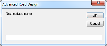 |
| New Surface Name Box |
Enter the name of the New surface in the box provided. |
| OK |
Create a surface with the new name. |
| Cancel |
Exit the form without creating a surface. |
|
 Copy Surface Copy Surface |
Creates a copy of the current surface, inclusive of all the Surface Inputs and Outputs.
An independent copy is created in this process.
Upon selecting the command the following form is displayed:
 |
| New Name Box |
Enter the name for the New surface in the box provided. |
| Height Change Box |
Enter a height change in metres (positive for up and negative for down) for the surface being copied in the box provided. |
| OK |
Create a copy of the current surface with the new name and height change, if entered. |
| Cancel |
Exit the form without creating a surface. |
|
| Surface Name Pick List |
Select any Surface from the list to enable editing and creation/output of the selected surface. |
 Pick from Drawing Pick from Drawing |
Pick a surface from the drawing to edit. |
 Delete Current Surface Delete Current Surface |
Deletes the currently highlighted surface.
Note: No confirmation warning message is displayed. |
 |
Click here to import a surface/s from a Land XML file. A navigation window will display to enable selection and opening of the file.
Upon selecting a Land XML file, the software will scan the file for all surfaces and include them in the Surfaces list.
Note: An imported surface cannot be edited by adding any Input data.
After the file has been opened the following is displayed:
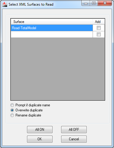 |
| Surfaces List |
This lists all of the Surfaces available for import from the Land XML file
chosen. |
| Surface Column |
Lists all the Surfaces in the Land XML file available form Import. |
| Add Column |
Tick the box to include the Surface/s for import into the Drawing. |
| Duplicate Name Options |
Provides control in cases where the Surface name being imported exists in the Drawing. |
| Prompt if duplicate name |
If the Surface name already exists, the following will be displayed:
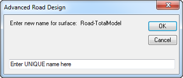 |
| New Name Box |
Space to enter a new unique name for the surface to be imported. |
| OK |
Create a surface with the new name. |
| Cancel |
Exit the form without Importing any data. |
|
| Overwrite duplicate |
If the Surface name exists, it will be deleted and lost and the Surface from the Land XML file will replace it. This is the default setting. |
| Rename duplicate |
If the Surface name exists, the surface being imported will be renamed with the suffix of "(x)", where x is a counter (number) starting from 1. |
| All ON |
Selects all the surfaces for import from the Land XML file. |
| All OFF |
De-selects all the surfaces. |
| OK |
Create a surface/s from the selected Land XML file. |
| Cancel |
Exit the form without Importing any data. |
|
 |
Exports the selected surface/s to a Land XML file, ready for import into other programs supporting the Land XML file format.
Upon selecting the command the following is displayed:
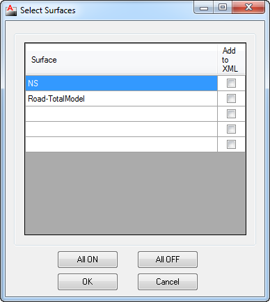 |
| Surfaces List |
This lists all of the Surfaces available for export to a LandXML file. |
| Surface Column |
Lists all the Surfaces in the drawing. |
| Include in XML Column |
Tick the box to include the Surface/s in the output Land XML file. |
| All ON |
Selects all the surfaces for export to Land XML file. |
| All OFF |
De-selects all the surfaces. |
| OK |
Create a Land XML file of the selected surfaces. By default, the exported file will by created in a folder named 'XMLExchangeFiles' located in the project data directory.
Note: By default, the Project Data Directory is located in the same folder as the current drawing, in a folder with the same name as the current drawing and with '-Data' suffix. |
| Cancel |
Exit the form without Exporting any data. |
|
 Zoom Extents Zoom Extents |
Zoom to the extents of the selected (current) surface. |
 Zoom and/or Pan Zoom and/or Pan |
Use the Mouse wheel to zoom and pan in the drawing. Press ESC to finish and return to the Create/Edit Surface form. |
 |
Forces the surface to redisplay - this is required when certain outputs are selected, such as slope arrows, slopes, heights and directions. |
 |
Create/Update the surface model. This forces a recalculation of the surface using all the data Inputs and a redisplay of the Outputs. |
 Help Help |
Display Help on this command. |
| Inputs Control (as shown above) |
Select all of the 3D data required for the construction of the surface. Upon selection of the Inputs Control tab a number of different surface input options will be displayed and include: |
| 3D Faces |

|
| AutoCAD Layer List |
Displays a list of AutoCAD layers that contain 3D face objects. |
 |
After selecting an AutoCAD layer containing 3D face objects, this button adds the layer as a data source in the Input List. |
 |
Creates a polyline that surrounds the 3D Faces. This polyline can then be used as a Boundary object. |
| Input List |
This lists all of the AutoCAD layers to be scanned for 3D faces to use in the creation of a surface. |
| Selection Column |
When a row is highlighted, a black arrow will display and the row will be highlighted.
Note: Pressing the Delete button after clicking on the black arrow will remove the layer entry from the list. |
| Layer Name |
Each Layer added as a source for 3D face data is listed. Each line can be selected however the line cannot be edited. |
|
| Points |
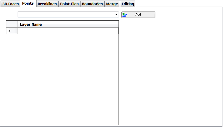
|
| AutoCAD Layer List |
Displays a list of AutoCAD layers that contain AutoCAD Point objects. |
 |
After selecting an AutoCAD layer, this button adds the layer as a data source in the Input List. |
| Input List |
This lists all of the AutoCAD layers to be scanned for AutoCAD Points (at Elevation) to use in the creation of a surface. |
| Selection Column |
When a row is highlighted, a black arrow will display and the row will be highlighted.
Note: Pressing the Delete button after clicking on the black arrow will remove the layer entry from the list. |
| Layer Name |
Each Layer added as a source for AutoCAD Point data is listed. Each line can be selected however the line cannot be edited. |
|
| Breaklines |
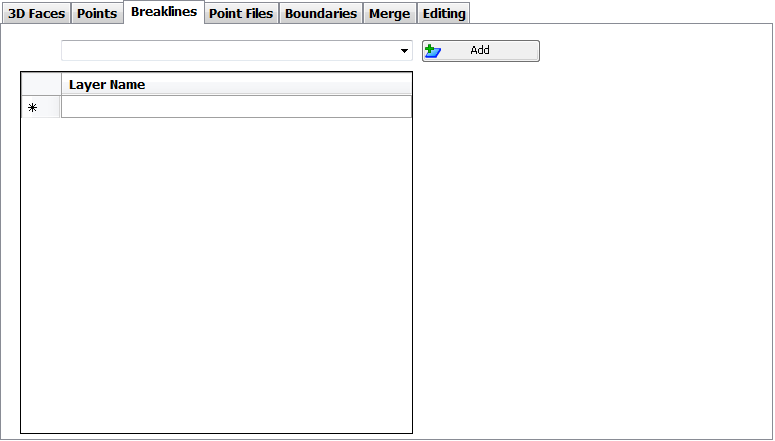
|
| AutoCAD Layer List |
Displays a list of AutoCAD layers that contain 3D Polyline objects. |
 |
After selecting an AutoCAD layer, this button adds the layer as a data source in the Input List. |
| Input List |
This lists all of the AutoCAD layers to be scanned for 3D Polylines (Breaklines) to use in the creation of a surface. |
| Selection Column |
When a row is highlighted, a black arrow will display and the row will be highlighted.
Note: Pressing the Delete button after clicking on the black arrow will remove the layer entry from the list. |
| Layer Name |
Each Layer added as a source for 3D Polyline data is listed. Each line can be selected however the line cannot be edited. |
|
| Point Files |
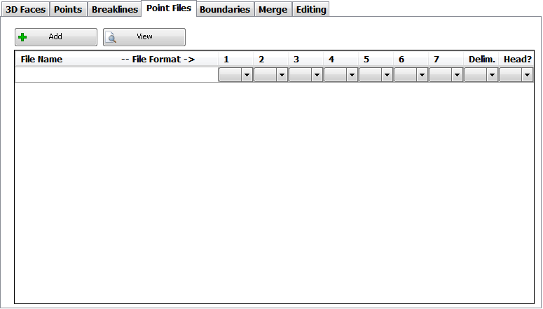
|
 |
After selecting this command, use the file search window to locate and open a Point File.
Note: The point file must have extension .txt to be selected. |
 |
After selecting a points file added in the Input List, use this button to open the file in Notepad to review the format. |
| File List |
This lists all of the added point files and the format of the file. Users need to look at the file structure, interpret each field of data and set this as the format for importing the file of data. The software will process data that is in an ASCII format, where each line in the file represents a single point and where each point's attributes (fields) are separated by a common delimiter. |
| File Name |
Lists all of the Added Point Files - Added using the Add Point File button.
Note: For each Added Point File, users need to set up how the file is to be interpreted. To delete a points file, select the File Name in the row and press the Delete button to clear the name and path |
| Field 1 to Field 7 |
Between 3 and 7 Fields may be required depending on the detail of information provided in the Points File. Each 'Field' correlates with the order that point data is expressed in the Point File.
Note: Use the View Point File button to open the file in Notepad to review the format of the file and ordering of point data in the file.
For each field, the user can assign whether the relative value in the file represents:
- PN = Point Number;
- X = X or Easting coordinate;
- Y = Y or Northing coordinate;
- Z = Elevation or Level;
- C = Chainage;
- <Skip> = Ignore data
|
| Delim |
Pick list to select the delimiter that separates the Field (point data) in the file. Supported delimiters include a comma, space, semi-colon, colon or Tab. |
| Head? |
Set whether the file includes a single line header row. More than 1 header row is not supported. If set to Yes the first row in the file is ignored. Default is No. |
|
| Boundaries |
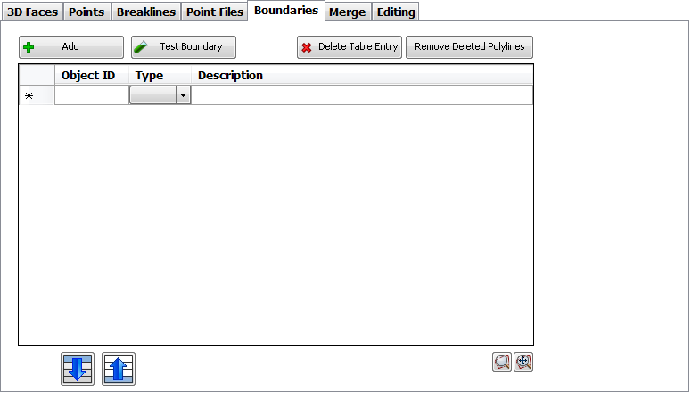
|
 |
After selecting this command, move into the drawing area and select a closed 2d polyline to apply it as a Boundary. |
 |
Tests how the boundary will be applied to the surface. |
 |
Deletes the selected or highlighted entry in the Boundary Input List. |
 |
Removes entries from the Boundary Input List, when the polyline no longer exists in the drawing. |
| Boundary Input List |
This lists all of the polylines that have been selected as surface boundaries. Users determine what type of boundary should apply. |
| Object ID |
This lists the AutoCAD polyline selected in the drawing by its object identification number - each object in AutoCAD in a drawing is given a unique identification number. This is a non-editable field. |
| Type |
Pick whether the boundary is:
- Outer = forming an outer extents for the surface. The surface will not be calculated outside of the boundary.
- Hide = this boundary type forces the surface to not be calculated (hide) inside the boundary.
- Show = this boundary type should occur AFTER a Hide boundary. It forces the surface to be calculated (show) inside the boundary.
|
| Description |
Users can type in a description for each added boundary. |
 Move Down Move Down |
Boundaries are processed in order in the list. A highlighted entry can be moved down the list using this button. |
 Move Up Move Up |
Boundaries are processed in order in the list. A highlighted entry can be moved up the list using this button. |
 Zoom to Boundary Zoom to Boundary |
Will zoom to the highlighted boundary entry in the drawing. |
 Show All Boundaries Show All Boundaries |
Will force display of all boundaries added to the surface. |
|
| Merge |
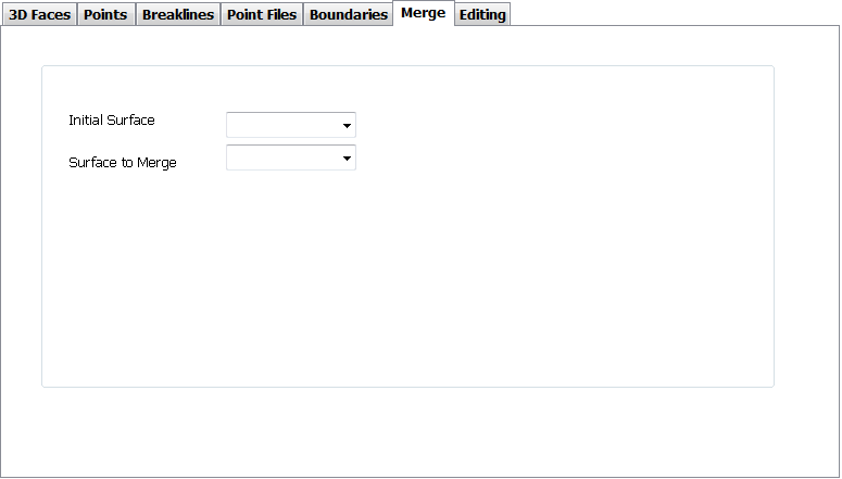
To use this command, first create a NEW surface, then choose the two (2) surfaces that are to be combined. The Initial Surface should be larger the the Surface to Merge. Once the 2 surfaces have been selected, press Build Surface.
|
| Initial Surface List |
Displays a list of Surfaces available to use as the first or base surface. |
| Surface to Merge |
Displays a list of Surfaces available to use that will be added and merge into the Initial. |
|
| Editing |
|
 |
Hover over this command button to expose the edit commands of Flip Side and Delete Edge. |
|
 |
Upon clicking this command, the user is prompted to select start point in the drawing. Use the mouse to select a triangle edge to flip. The entry will be added to the Edits List. |
 |
Upon clicking this command, the user is prompted to select a start and end point in the drawing. Click twice to cross the triangles that are to be removed from the surface. The entry will be added to the Edits list |
|
 |
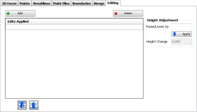
Deletes the highlighted entry in the Edits Applied list. |
| Edits Applied List |
Each edit is listed here. |
 Move Down Move Down |
Edits are applied top down in the list. Click here to move a highlighted entry down in the list |
 Move Up Move Up |
Edits are applied top down in the list. Click here to move a highlighted entry down in the list |
| Height Adjustment |
Provides a way to raise or lower an entire surface, |
| Raise/Lower by |
Enter a height change in metres (positive for up and negative for down). |
 |
After a Raise/Lower has been entered in the box above, use this button to Apply the change. |
| Height Change |
Displays what Height Change has already been applied to the surface. |
|
| Outputs Control |
The Outputs Control tab sets out how the surface should display in the drawing, as well as controlling how the surface is built. Upon selection of the Outputs Control tab a number of different surface options will be displayed and include: |
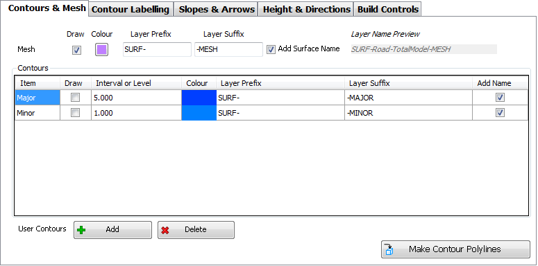
| Contours & Mesh |
|
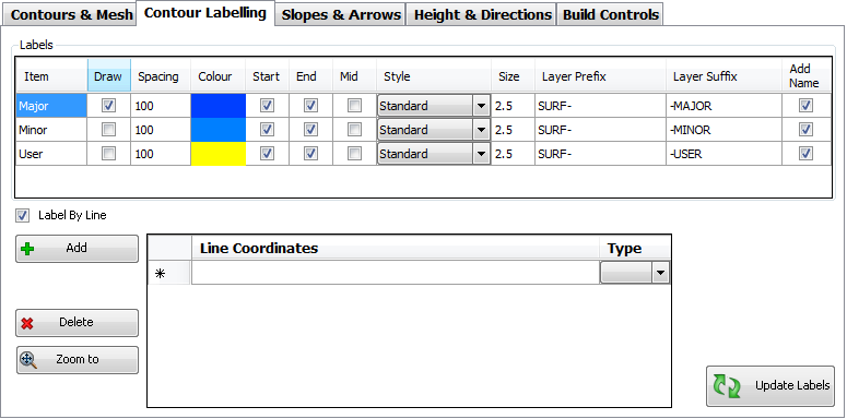
| Contour Labelling |
|
| Slopes & Arrows |
When selecting this tab for the first time tab, the default for both options is OFF, so that image below does not represent the 'start' condition. Once the Show box is ticked, the information, as shown, will be displayed.
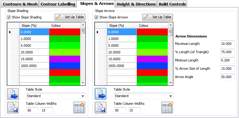 |
| Slope Shading |
| Show Slope Shading |
Tick On/Off to include Slope Shading. If turned ON, the following options will appear, otherwise the area below will be 'blank'. |
 |
Use this option to generate a table based on surface statistics. Refer separate help on this item. |
| Slope Shading List |
List of slope values and colours to apply over the range. The range is defined from one slope value to the next slope value in the list. |
| Slope (%) |
Type in a slope value (percent grade) |
| Colour |
Click in the cell to select a Colour to apply. Note: ByLayer or ByBlock cannot be selected |
 Load Style Load Style |
Loads a user defined list of values and colours. |
 Save Style Save Style |
Create a new saved list of values and colours for loading into any project. |
| Table Style |
Use the pick list to select the Table Style to apply before Create Table is used. Only a two (2) column table is created. |
| Table Column Widths |
Enter the width for each Column. The left hand box is for the range and the right hand box is for the colour. |
 Create Table Create Table |
Create an AutoCAD table in the drawing. The table style and widths will be based on the values selected. The table will have a title, heading and data rows matching the
information shown. The first column will display the range, the second column will display the colour matching the range. Should the Table already exist, selecting this button will
update the existing table. |
|
| Slope Arrows |
| Show Slope Arrows |
Tick On/Off to include Slope Arrows. If turned ON, the following options will appear, otherwise the area below will be 'blank'. |
 |
Use this option to generate a table based on surface statistics. Refer separate help on this item. |
| Slope Arrow List |
List of slope values and colours to apply over the range. The range is defined from one slope value to the next slope value in the list. |
| Slope (%) |
Type in a slope value (percent grade) |
| Colour |
Click in the cell to select a Colour to apply. Note: ByLayer or ByBlock cannot be selected |
 Load Style Load Style |
Loads a user defined list of values and colours. |
 Save Style Save Style |
Create a new saved list of values and colours for loading into any project. |
| Table Style |
Use the pick list to select the Table Style to apply before Create Table is used. Only a two (2) column table is created. |
| Table Column Widths |
Enter the width for each Column. The left hand box is for the range and the right hand box is for the colour. |
 Create Table Create Table |
Create an AutoCAD table in the drawing. The table style and widths will be based on the values selected. The table will have a title, heading and data rows matching the
information shown. The first column will display the range, the second column will display the colour matching the range. Should the Table already exist, selecting this button will
update the existing table. |
| Arrow Dimensions |
Allows the user to control how the arrow size is managed in the drawing. Slope arrows are drawn at the centroid of each triangle of the surface. |
| Maximum Length |
Sets the maximum length of the slope arrow. Note: Set the Maximum Length and Minimum Length to be the same if equal sized arrows are desired at every triangle. |
| % Length (of Triangle) |
Use this to set the length of the arrow to be a factor of the size of the triangle. The length is determined by drawing an inscribed circle through the corners of the triangle and measuring the diameter of the circle. The % value set here (between zero and 100) is multiplied by the diameter of the inscribed circle to establish the length of the line.
Note: The calculated length will be limited to no more than the Maximum Length and no less than the Minimum Length |
| Minimum Length |
Sets the minimum length of the slope arrow. Note: Set the Maximum Length and Minimum Length to be the same if equal sized arrows are desired at every triangle. |
| % Arrow Size of Length |
This controls the size of the arrow portion, measured as a % of the total line length. Type a value between zero and 100. |
| Arrow Angle |
Two short lines are used to describe the arrow head - set the angle of the arrow head. |
|
|
| Height & Directions |
When selecting this tab for the first time tab, the default for both options is OFF, so that image below does not represent the 'start' condition. Once the Show box is ticked, the information, as shown, will be displayed.
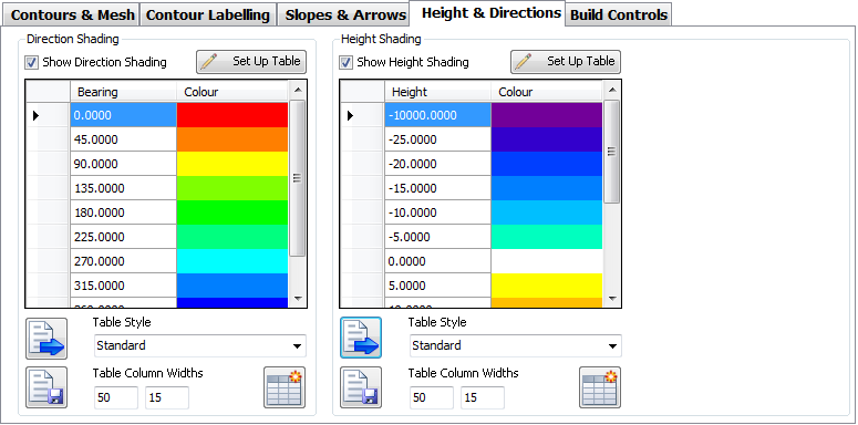 |
| Height Shading |
| Show Height Shading |
Tick On/Off to include Height (Elevation) Shading. If turned ON, the following options will appear, otherwise the area below will be 'blank'. |
 |
Use this option to generate a table based on surface statistics. Refer separate help on this item. |
| Height Shading List |
List of elevations (heights) and colours to apply over the range. The range is defined from one height value to the next height value in the list. |
| Height |
Type in a elevation value. |
| Colour |
Click in the cell to select a Colour to apply. Note: ByLayer or ByBlock cannot be selected |
 Load Style Load Style |
Loads a user defined list of values and colours. |
 Save Style Save Style |
Create a new saved list of values and colours for loading into any project. |
| Table Style |
Use the pick list to select the Table Style to apply before Create Table is used. Only a two (2) column table is created. |
| Table Column Widths |
Enter the width for each Column. The left hand box is for the range and the right hand box is for the colour. |
 Create Table Create Table |
Create an AutoCAD table in the drawing. The table style and widths will be based on the values selected. The table will have a title, heading and data rows matching the
information shown. The first column will display the range, the second column will display the colour matching the range. Should the Table already exist, selecting this button will
update the existing table. |
|
| Direction Shading |
| Show Direction Shading |
Tick On/Off to include Direction Shading. If turned ON, the following options will appear, otherwise the area below will be 'blank'. |
 |
Use this option to generate a table based on surface statistics. Refer separate help on this item. |
| Direction Shading List |
List of bearings values and colours to apply over the range. The range is defined from one bearings value to the next bearings value in the list. All
bearings are measured relative to the North direction in the drawing. |
| Bearing |
Type in a bearing direction in decimal degrees. |
| Colour |
Click in the cell to select a Colour to apply. Note: ByLayer or ByBlock cannot be selected |
 Load Style Load Style |
Loads a user defined list of values and colours. |
 Save Style Save Style |
Create a new saved list of values and colours for loading into any project. |
| Table Style |
Use the pick list to select the Table Style to apply before Create Table is used. Only a two (2) column table is created. |
| Table Column Widths |
Enter the width for each Column. The left hand box is for the range and the right hand box is for the colour. |
 Create Table Create Table |
Create an AutoCAD table in the drawing. The table style and widths will be based on the values selected. The table will have a title, heading and data rows matching the
information shown. The first column will display the range, the second column will display the colour matching the range. Should the Table already exist, selecting this button will
update the existing table. |
|
|
| Build Controls |
Users can control how data is processed in the creation of the surface.
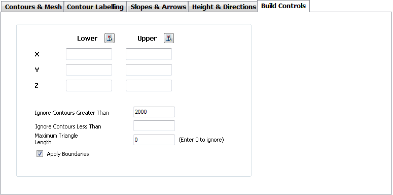 |
| Bounds - Lower
- Upper |
Bounding limits and levels can be set. Enter:
- X (Easting);
- Y (Northing) and
- Z (Elevation/Level) for the Lower and Upper bounds.
Alternatively, use the Pick Co-ordinate button  provided for each bound column. provided for each bound column. |
| Ignore Elevations Greater Than |
Type an elevation - any data with a z value above this figure will not be included in the surface modelling. |
| Ignore Elevations Less Than |
Type an elevation - any data with a z value below this figure will not be included in the surface modelling. Setting this to a value above zero will automatically exclude zero elevation data from the build process. |
| Maximum Triangle Length |
Type a maximum triangle length to have the surface triangulation adjust, with triangles being removed when any edge of the triangle exceeds this value. Set to zero to ignore maximum triangle length controls. |
| Apply Boundaries |
Tick on to apply boundaries as set up in the Input > Boundaries tab. |
|
 Load Style Load Style |
Loads a pre-set Surface Style - the Surface Style sets Output controls for the surface. |
 Save Style Save Style |
After setting up the Outputs as desired, use Save Style to store the Output settings for re-use. |
| Loaded Style: |
After Load Style has been used, the SDF filename loaded is displayed here. |
| Statistics |
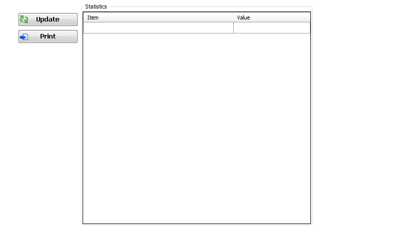
Displays Statistics about the surface. Upon selecting the Statistics Control tab, the following form is displayed. The form is initially empty, data will only appear after the Update
button has been selected. |
|
 |
 |
Press to calculate various statistics for the surface. Statistics include: Elevations; Triangles, Area etc. |
 |
Create a Surface Statistics report - the report outputs to Notepad. A file, with a name of "Statistics-SurfaceName.txt" is created and stored in the Temp sub-folder
under the Project Data directory. |
| Statistics List |
List of statistics and data for the Surface once calculated. |
| Item |
Description of statistics, data or item calculated. |
| Value |
Numerical value matching the Item. |
|
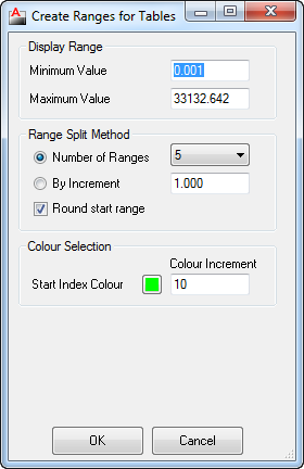
For each of the four (4) analysis that can be carried out on a surface, this option provides a way to generate the ranges based on the statistics for the surface being analysed.

 New Surface
 Copy Surface
 Pick from Drawing
 Delete Current Surface

 Zoom Extents
 Zoom and/or Pan

 Help
Help Load Style
 Save Style


 Move Down
 Move Up
 Zoom to Boundary
 Show All Boundaries





 Load Style
 Save Style
 Create Table

 provided for each bound column.

