General Settings
Details
This is a core setting and must be added once to establish the general plotting controls.
Users establish the plot direction (upstream or downstream), the pit layer and the pit width to be displayed.
This also provides an override control for vertical and horizontal band lines for checking line work options.
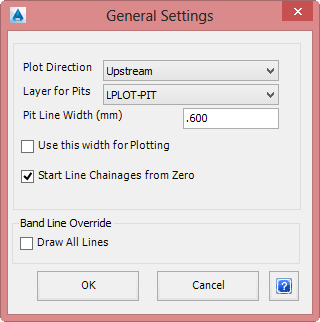
Upon selecting the the command the following form is displayed:
|
|
| Plot Direction | From the drop down list select either Downstream or Upstream. If Downstream is selected, the pipes will be drawn with the nominated outflow pit on the left and pipes drawn to the right. If Upstream is selected, the pipes will be drawn working from the pit furthest from the outflow pit and pipes drawn to the right toward the outflow pit. |
| Layer for Pits | From the drop down list select the required layer to display the repeated pits. Use the Edit Layer Settings command to edit the layers available. |
| Pit Line Width (mm) | In the box provided enter the plotted width of pits in millimetres. This will be applied to all pits, except pits in the NULL pit family. |
| Use this width for Plotting | Applies only to Sewer Manholes. If ticked on, the Pit Line Width is used for plotting all Sewer pits. |
| Start Line Chainages from Zero | Tick this option on to start each line/branch of the network being plotted at Chainage 0. |
| Band Line Override | |
| Draw All Lines | Check this box to override and draw all vertical and horizontal band lines, regardless of the settings in either of the Pit or Pipe Items band control. This can be useful as a check. |
| OK | Apply the settings controls and exit. |
| Cancel | Exit the form without making any changes. |