CAD Output (Import Objects/Import MV Data)
Icon: ![]()
Ribbon: Site
tab > Model viewer panel > Import Objects
Roads
tab > Select Panel > Model Viewer Dropdown > Import MV Data
General
tab > 3D View Panel > Model Viewer Dropdown > Import MV Data
Model Viewer Icon: ![]()
Model Viewer Ribbon: Model Viewer > Outputs > CAD Output
Introduction
The CAD Output command allows users to output Model Viewer created objects into model space as CAD entities. Model Viewer objects that can be outputted to CAD include:
1. Line-marking created by using the Line-Marking command.
2. Sight distance lines created by using the Sight Distance command.
3. 3D Objects (outputted as AutoCAD/BricsCAD Blocks) created using the Import Objects command.
Details
Upon selecting the command the following form is displayed:
|
|
Output |
|
| Line Marking | Specify whether line-marking entities created by the Model Viewer Line-Marking command will be outputted to model space. |
| Sight Distance | Specifiy whether sight distance line entities created by the Model Viewer Sight Distance command will be outputted to model space. |
| 3D Objects | Specify whether 3D objects created using the Model Viewer Import Object command will be outputted to model space (as AutoCAD/BricsCAD Blocks). |
Line Marking Table |
This table lists all used line-marking styles for the current project. This table is shown in the screenshot above. |
| Toggle On/Off | Specify whether line-marking that references the specified style will be outputted to model space. |
| Style | The name of the line-marking style. |
| Layer | The AutoCAD/BricsCAD Layer that the outputted CAD entities will be created on. |
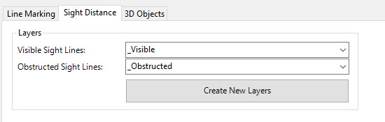
Sight Distance (Assign Layers) |
Allows the user to specify AutoCAD/BricsCAD Layers for the outputted sight distance lines. |
 |
|
| Visible Sight Lines (Layer) | Specify the AutoCAD/BricsCAD Layer for 'visible' sight distance lines |
| Obstructed Sight Lines (Layer) | Specify the AutoCAD/BricsCAD Layer for 'obstructed' sight distance lines. |
| Create New Layers | This command will create two new AutoCAD/BricsCAD Layers in the drawing named '_Visible' and '_Obstructed'. These Layers have been created with colours (green for visible and red for obstructed sight lines) and assigned in the fields above. |
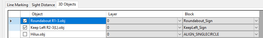
3D Objects Table |
This table list all 3d objects that have been imported into Model Viewer. |
 |
|
| Toggle On/Off | Specify whether the CAD entities for the specified 3D object will be outputted. |
| Layer | Specify the AutoCAD/BricsCAD Layer that the Block will outputted on. |
| Block | Specify the Block (must exist in the current drawing), that will be used to represent the 3d Object in model space. |
| Allows the user to save the CAD Output form. This means that users can use these output settings in other Civil Site Design projects. | |
| Allows the user to open previously saved CAD Output settings. | |
| Update Output on Model Viewer Refresh | If this option is ticked on, then the geometry of the CAD entities outputted will update on Model Viewer Refresh. |
| Reset | Deletes the current CAD Output setup. This command might be used if corruption occurs with the current output. |
| Output | Outputs the CAD entities as per the settings defined in the CAD Output form. |
| Close | Exits the form. |
