Plot Plan of Road
Icon: ![]()
![]()
Menu: Roads > Plot Plan of Road
Ribbon: Roads Tab > Plan Production Panel > Plot Plan of Road
Introduction
This command allows the Designer to plot a plan of the road on the drawing by extracting all the horizontal geometry strings from one selected road and plotting them as polylines.
By default the command will plot the following codes as polylines for both sides of the road (left and right):
- C.L.
- EB
- INV
- TK
- BK
- FPI
- FPO
- BAT
Details
This command is used to plot plan features of road objects in the modelspace.
On starting the command the Designer is prompted to select an alignment or press [Enter] to select from a list.
Upon selecting a road the following form is displayed:
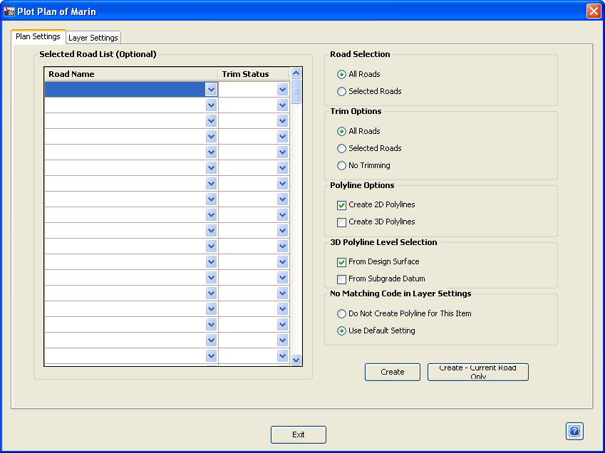 The Plan Settings tab gives the user the option to choose which roads will be plotted, whether the roads will be trimmed, the type of polylines created and finally choose whether to apply the plotting to the modelspace. |
|
| Road Selection | Choose whether to plot all the roads in the drawing file or just roads listed in the Selected Road List. |
| All Roads | Click to plot all the roads in the drawing file. |
| Selected Roads | Click to only plot roads that are listed in the Selected Road List. |
| Trim Options | Choose whether to trim the plotted polylines where intersections and kerbs have been created. |
| All Roads | Click to trim all roads in the drawing. This is only relevant if All Roads has been chosen in Road Selection. |
| Selected Roads | Click to trim roads as specified in the Selected Road List. This is only relevant if Selected Roads has been chosen in Road Selection. |
| No Trimming | Click to exclude trimming when plotting the polylines. |
| Polyline Options | Choose whether to create 2D or 3D polylines. |
| Create 2D Polylines | Tick this box to create 2D polylines. |
| Create 3D Polylines | Tick this box to create 3D polylines. |
| 3D Polyline Level Selection | Choose whether to determine the level of the 3D polyline from the Design Surface or the Subgrade Datum. This is only relevant if the Create 3D Polyline option is ticked. |
| From Design Surface | Tick this box to determine the polyline level in reference to the Design Surface. |
| From Subgrade Datum | Tick this box to determine the polyline level in reference to the Subgrade Datum. |
| No Matching Code in Layer Settings | If the Designer has created a new code that isn't detailed in the Layer Settings, the program will need to be told how to treat it. |
| Do Not Create Polyline for this Item | Click to exclude polylines for codes that are not specified in Layer Settings. |
| Use Default Setting | Click to create polylines for codes that are not specified in Layer Settings by using the default settings. |
| Selected Road List (Optional) | Fill in this table if Selected Roads has been chosen in Road Selection. Specify which roads to plot and their respective trim status. |
| Road Name | Use the pick list to select the roads to plot polylines on. |
| Trim Status | Use the pick list to specify whether the polylines should be trimmed or not (Yes/No). |
| Create | Click to plot the plans as per the settings detailed above. |
| Create - Current Road Only | Click to plot the plan for the road selected at the beginning of the command. |
| Exit | Exit the form without making any changes. |
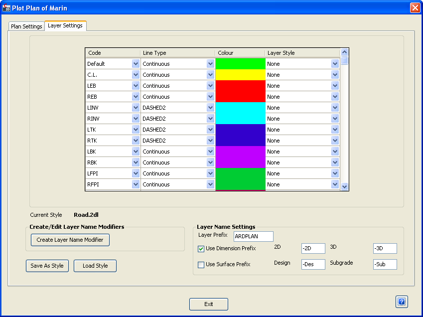
Click the Layer Settings tab at the top of the form to specify the colours and naming convention of the polylines created.
Upon selecting the tab the following form is displayed:
 |
|||||||||||||||||||||||||||||||||||||||||
| Table | Use the table to determine the colour and line style of the polyline created for each respective code. | ||||||||||||||||||||||||||||||||||||||||
| Code |
Lists the Codes used in the drawing. Use the pick list to
choose a code to alter the settings of. Note: 'Default' will be used when a code exists in the drawing, is not specified in this list and Use Default Setting has been selected from the options under No Matching Code in Layer Settings. |
||||||||||||||||||||||||||||||||||||||||
| Line Type | Use the pick list to choose the line type. For instance, whether the line is solid and continuous or whether it is dashed. | ||||||||||||||||||||||||||||||||||||||||
| Colour | Click to select or change the colour of the line. | ||||||||||||||||||||||||||||||||||||||||
| Layer Style | Use the pick list to choose the layer style to be applied. | ||||||||||||||||||||||||||||||||||||||||
| Current Style | This mentions the name of the style currently in use. | ||||||||||||||||||||||||||||||||||||||||
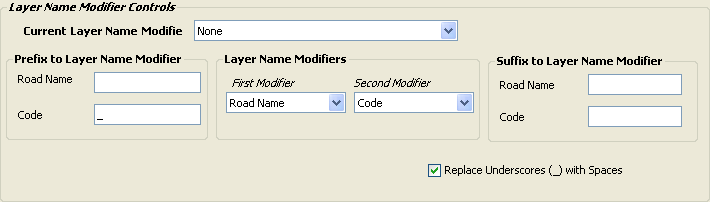
| Create/Edit Layer Name Modifiers | Use these settings to modify the naming convention for the layers created for the polylines. | ||||||||||||||||||||||||||||||||||||||||
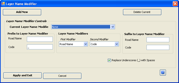
| Create Layer Name Modifier |
Use this command to create or edit a Layer Name Modifier. After clicking the button, the following form is displayed:
|
||||||||||||||||||||||||||||||||||||||||
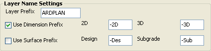
| Layer Name Settings | Sets the naming prefix for the layers created. | ||||||||||||||||||||||||||||||||||||||||
| Layer Prefix | The text entered here will be the prefix for the name of the layers created. For instance, if 'ARDPLAN' is entered, then all new layers created for the polylines will begin with the text 'ARDPLAN'. | ||||||||||||||||||||||||||||||||||||||||
| Use Dimension Prefix | Tick this box to have a dimension prefix (2D or 3D) included in the layer name. This prefix will come after the Layer Prefix. | ||||||||||||||||||||||||||||||||||||||||
| Use Surface Prefix | Tick this box to have a surface prefix (Design or Subgrade) included in the layer name. This prefix will come after the Layer Prefix or the Dimension Prefix (if present). | ||||||||||||||||||||||||||||||||||||||||
| Save As Style | Click to save the current style so it can be accessed (via Load Style) at a later time. This command saves everything under the Layer Settings tab, except the Layer Name Modifiers. | ||||||||||||||||||||||||||||||||||||||||
| Load Style | Click to load a preexisting or previously saved style. | ||||||||||||||||||||||||||||||||||||||||
| Exit | Exit the form without making any changes. | ||||||||||||||||||||||||||||||||||||||||
 |
|
Shown above is an example of the layer names of a plan
plotted with the following layer settings:
|
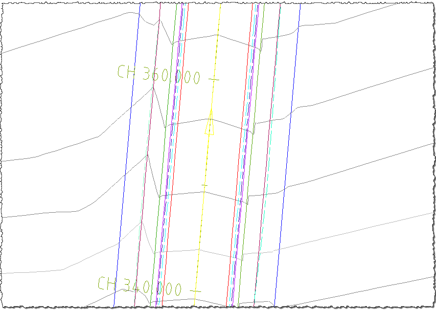 |
| Shown above is an example of the output created from the Plot Plan of Road command. |