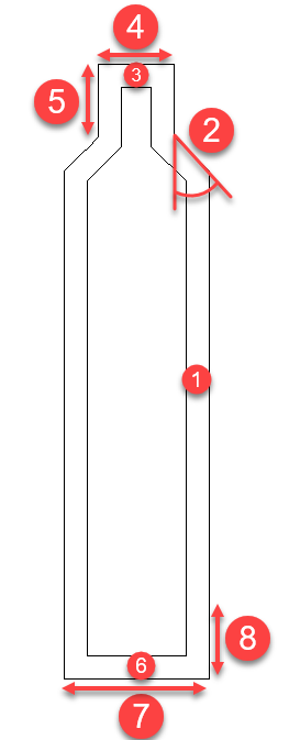
Profile Structure Styles
Icon: ![]()
![]()
Menu: Pipes > Settings > Profile Structure Styles
Ribbon: Production Tab > CAD Pipe Production Panel > Profile Views
Dropdown > Profile Structure Styles
Pipes
tab > Settings Panel > Setting Dropdown > Profile Structures
Introduction
Users can use this tool to specify how manholes and inlets should be presented on the profile view.
In the Active Network Settings (and Global Network Settings) form there is a picklist when creating structures to assign the profile view representation of the structure.
Details
Upon selecting the command the following form is displayed:
|
|
Current Item |
Pick the Profile View Structure Style to edit |
Add |
Add a new style |
Delete |
Delete a selected style |
Wall thickness |
Thickness of walls, between the 'top' and 'bottom' sections |
Top is Fixed/Bottom is Fixed |
Users can have a fixed height section from the top down, or from the bottom up. This is relevant for tapered structures |
Taper Angle |
Leave at zero if the Top size and Bottom size are identical. Otherwise specify an angle greater than 0 and less than or equal to 90 degrees. |
| Top | Define top section of structure. Assumes vertical walls for the Height |
Top thickness |
Thickness of the top (lid) |
Diameter/Width and Length |
Pick diameter for cylindrical structures. Specify
a diameter Pick Width and Length for rectangular structures. Specify a width and length |
| Height | Fixed height from the Top of structure down. |
| Bottom | Define bottom section of structure. Assumes vertical walls for the Height |
Bottom thickness |
Thickness of the bottom of the structure (floor) |
Diameter/Width and Length |
Pick diameter for cylindrical structures. Specify
a diameter Pick Width and Length for rectangular structures. Specify a width and length |
Height |
Fixed height from the Bottom of the structure up |
OK |
Apply and exit. |
Cancel |
Exit the form without change |
All structures are saved to the CSD Settings folder (they are globally edited and globally available on every project).

