DRAINS Overflows
Icon:
![]()
Menu: ARD Pipes > Create Drainage... > DRAINS Overflows
Ribbon: Pipes Tab > Drainage Design Panel > Bypass and Overflows Dropdown > DRAINS Overflows
Introduction
In Civil Site Design, users can specify Structure Bypass routes to allow for flows that don't enter a structure (due to limiting structure inlet capacities) to be diverted to downstream structure/s. DRAINS supports Overflow Routes to serve a similar (and expanded) purpose.
In DRAINS, an overflow route describes the typical cross section applying from one node/input to another node/input. Flow is calculated in the overflow route in order to determine the safe depth of flow. DRAINS allows designers to assign a percentage of the downstream catchment flow to apply to the Overflow Route, as well as supporting ponding and backwater effects in the Premium Model of DRAINS.
Civil Site Design will create Overflow Routes connecting from upstream structures to downstream structures during a DRAINS export. This form allows users to assign key inputs to apply when the Overflow Route is created during export, for each structure bypass.
List of Overflow Route Templates
A list of available Overflow Route templates will be displayed - this is read directly from the following location and file:
C:\ProgramData\Drains\Drains Connection Data.txt
If DRAINS is installed on the computer, this file is automatically created by DRAINS and describes the default database of Pits, Pipes and Overflow Routes that can be used on a DRAINS project. In order to get the most out of this functionality, it is recommended that DRAINS operators establish all the default items they would have in a project and save it to the default database (Drains.db1).
In DRAINS, creating a new structure,pipe or overflow route template will trigger a prompt to save the item/s to the DRAINS database (Drains.db1) - this will add the item to the Drains Connection Data.txt file and make it available to use in the export to DRAINS. The Drains.db1 fiel is used each time you start a new file.
If DRAINS is not installed on the computer, the above file should be copied from a computer that has DRAINS installed and placed on the computer from which this command will be run.
What Happens If I Don't Assign a Drains Section?
If a DRAINS Overflow Route Template (Drains Section) is not selected, then a default overflow route template (named ARD) will be assigned to the overflow route/s during export.
Length of Overflow Route
By default, the export process assumes a straight line for the overflow route, connecting from an upstream structure to a downstream structure. the overflow route may, however travel on a circuitous path from the upstream structure to the downstream structure. Users are able to select a polyline to describe the general path of the overflow route - this will populate the Length in DRAINS.
DS Area % = % of downstream catchment flow carried by this channel in DRAINS
In DRAINS, users can assign a percentage of the catchment at the downstream of the overflow route to apply to the overflow route channel. This command supports assignment of this percentage - the column named DS Area % can be used to populate this value in the overflow route in DRAINS.
Details
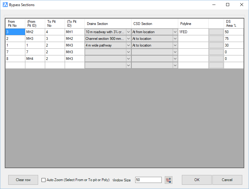
Upon selecting the command the following form is displayed:
|
|
|
|
Overflow Route List |
This list describes every Structure Bypass and enables configuration for Overflow Routes to be created |
|
From Structure No. |
Non-editable field describing the structure connecting to the start of the structure bypass. This is the unique ID number for the structure as assigned by the software. |
|
From Structure ID |
Non-editable field describing the structure connecting to the start of the structure bypass. This is the label assigned to the structure by the user. |
|
To Structure No. |
Non-editable field describing the structure connecting to the end of the structure bypass. This is the unique ID number for the structure as assigned by the software. |
|
To Structure ID |
Non-editable field describing the structure connecting to the end of the structure bypass. This is the label assigned to the structure by the user. |
|
Drains Section |
Select the Overflow Route Template to apply during export, using the pick list. List populated from the file C:\ProgramData\Drains\Drains Connection Data.txt |
|
CSD Section |
This field is not currently used. The pick list allows for assignment of a cross section to the structure bypass by calculating a section at the start or end of the bypass, or by selecting a Cross Section Template |
|
Polyline |
To assign a polyline to use for the length, click on the box with three dots (...) to the right of the Polyline field and select a polyline in the drawing. The unique ID of the polyline will be populated in the Polyline field - this is non-editable except by clicking on the box to the right of the Polyline field and selecting a different polyline in the drawing. |
|
DS Area% |
Type in a value between zero and 100 |
|
Clear Row |
This will remove all overflow route export information from the highlighted overflow route. |
| Auto Zoom | Tick on to zoom in the drawing to structures selected in the list. |
| Window Size | Sets a zoom window for the selected structure. |
|
Allows zooming and panning in the drawing (form temporarily closes). Clicking the left or right mouse button or pressing on the keyboard will return to the form. |
|
|
OK |
Apply and exit. |
|
Cancel |
Exit the form without applying any changes |