
|
File |
|
Import Settings |
The Project Assist settings can be loaded from file. After
clicking on this button, select a saved Project Assist
Settings (*.dat) to populate the form. |
|
Export Settings |
The Project Assist settings can saved to file for re-use on any
project. After clicking on the button, type in a name to
save the Project Assist Settings to file (*.dat). |
|
Default
Templates Tab |
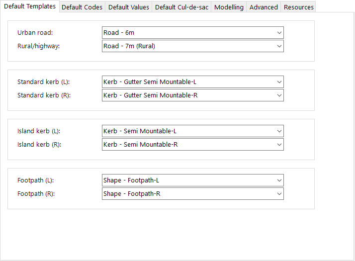
For the different types of Strings that Project Assist
creates, users can select the default Templates to use
by default
|
Urban
road |
Select
the default Template. |
Rural/Highway |
The
software will intelligently assess the alignment name
to determine whether to apply this Template or the Urban
Road template.
Select the default Template. |
Standard
Kerb (L) |
This
will be applied to Strings that are associated to a road
edge, and strings not associated with a road edge. This
is for templates that apply left of the Road string alignment,
or on the right of the alignment if running in the reverse
direction of the Road String
Select the default Template. |
Standard
Kerb (R) |
This
will be applied to Strings that are associated to a road
edge, and strings not associated with a road edge. This
is for templates that apply right of the Road string alignment,
or on the left of the alignment if running in the reverse
direction of the Road String
Select the default Template. |
Island
Kerb (L) |
This
will be applied to Strings that are associated to an island
or central roundabout. This will apply to alignments
going in an anti-clockwise direction
Select the default Template. |
Island
Kerb (R) |
This
will be applied to Strings that are associated to an island
or central roundabout. This will apply to alignments
going in a clockwise direction
Select the default Template. |
Standard
Footpath (L) |
This
will be applied to Strings that are associated with the
Footpath codes on a road string. This applies
left of the Road string alignment, or on the right of
the alignment if running in the reverse direction of the
Road String
Select the default Template. |
Standard
Footpath (R) |
This
will be applied to Strings that are associated with the
Footpath codes on a road string. This applies
right of the Road string alignment, or on the left of
the alignment if running in the reverse direction of the
Road String
Select the default Template. |
|
Default
Codes Tab |
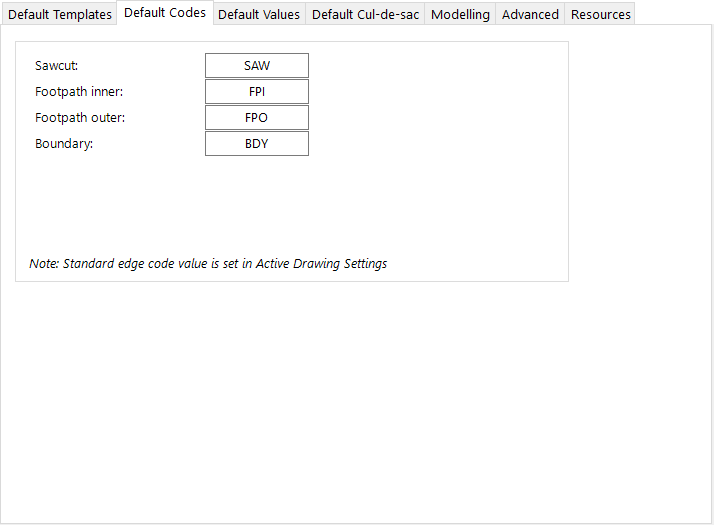
Project Assist supports specific actions for alignments/strings
to include pavement saw cuts, manage footpath inner or
outer location and to edit the boundary (batter/daylight
extents). It is expected these codes will exist
on the Template assigned to the associated Road String. The
Road Edge Code is taken from the Active Drawing
Settings command. |
Sawcut |
Where
users set a Sawcut control, the alignment will be used
to adjust the selected Code (the Code specified does not
include the L/R prefix) on the Template applied to the
Road String |
Footpath
(Sidewalk) Inner |
Where
users set a footpath control, the innermost alignment
will define the inside edge of the footpath and will be
used to adjust the selected Code (the Code specified does
not include the L/R prefix) on the Template applied to
the Road String
Note: where only one alignemnt is designated as a Footpath
on a road side, it will always be treated as a control
for the inner edge of the footpath |
Footpath
(Sidewalk) Outer |
Where
users set two footpath controls on a side of a Road String,
the outermost alignment will define the outside edge of
the footpath and will be used to adjust the selected Code
(the Code specified does not include the L/R prefix) on
the Template applied to the Road String |
Boundary |
Where
users set a Boundary control, the alignment will be used
to adjust the selected Code (the Code specified does not
include the L/R prefix) on the Template applied to the
Road String |
|
Default
Values Tab |
|
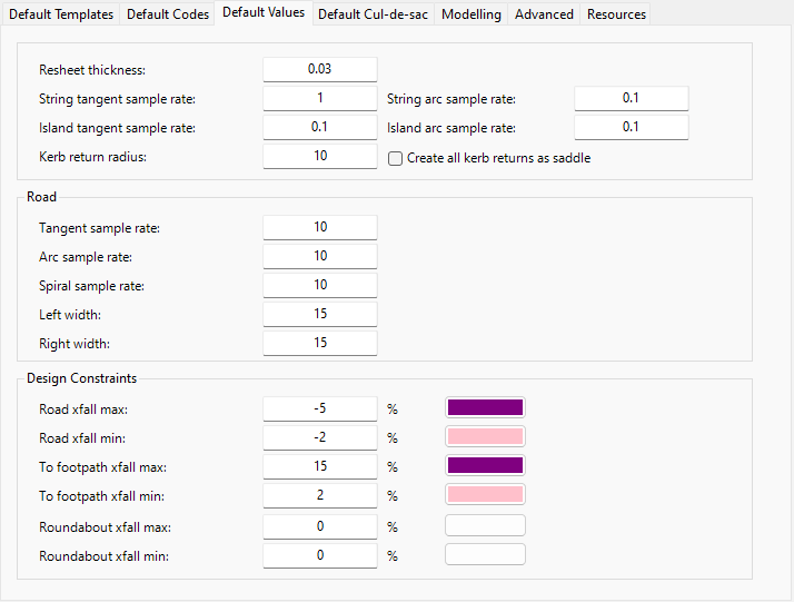
Resheet
Thickness |
Where
conditions are satisfied for a Resheet to be available
for a Road string, this will be the default thickness
(changeable by the user at the time of creating the road
string) |
String
Sample Rate |
Where
a String is being added to the design, this is the default
sample rate. |
|
Island
Sample Rate |
Where
an Island string is being added to the design, this is
the default sample rate. |
|
Kerb
(Curb) Return Radius |
At
intersections where no kerb (curb) alignment has been
created by the user and selected to be used, this will
display as the defualt radius for creating returns at
all other intersections. |
|
String arc sample rate |
Sampling rate to apply to created Profile Strings |
|
Island arc sample rate |
Sampling increment to apply to Island Strings |
|
Create all kerb returns as saddle |
Tick on to default for all kerb return intersections to be 'All
Crowned' (no primary road control). |
Road |
Default settings that apply to Road
Strings |
|
Tangent
Sampling Rate |
Sampling
interval along tangents |
|
Arc
Sampling Rate |
Sampling
interval along arcs |
|
Spiral
Sampling Rate |
Sampling
interval along spirals |
|
Left
Width |
Width
of surface sampling left of the alignment. Important
for calculating volumes and batters/daylights |
|
Right
Width |
Width
of surface sampling right of the alignment. Important
for calculating volumes and batters/daylights |
Design Constraints |
The software will automatically
create design constraints to help users manage crossfalls
when undertaking string design |
|
Road
xfall max |
Applies
to strings created for the road edge. Type
a value and click on the colour swatch to set a colour. |
|
Road
xfall min |
Applies
to strings created for the road edge. Type
a value and click on the colour swatch to set a colour. |
|
Road footpath
xfall max |
Applies to strings created to control
the offset and elevation of footpath. Type
a value and click on the colour swatch to set a colour. |
|
Road
footpath xfall min |
Applies
to strings created to control the offset and elevation
of footpath. Type a value and click on the
colour swatch to set a colour. |
|
Default
Cul-de-sac Tab |
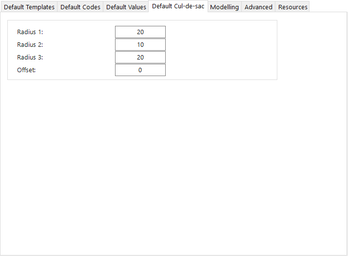
Users can elect to have the software add circular cul-de-sacs
at the start/end of each Road String. The cul-de-sac
wil be placed so the head of the bowl is close to the
start/end of the alignment. Default sampling
and transfer elevations will be assumed. |
Radius
1 |
Entry
radius for the cul-de-sac |
Radius
2 |
Bowl
radius for the cul-de-sac |
Radius
3 |
Return
radius for the cul-de-sac |
Offset |
Optional
offset for the centrepoint of the Radius 2. The
offset must be less than Radius 2. Positive
values will offset to the right of the alignment and negative
values to the left. |
|
Modelling
Tab |
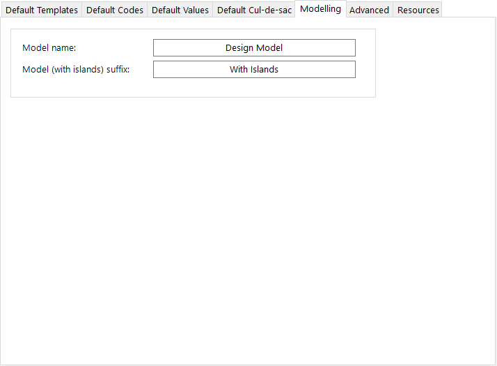
Project Assist will create multiple Models to best
create the design:
- Where independent strings are being included, these
are added to a design model. This design
model is built on the TotalModel, where road and road
network strings are included
- Where islands are included (median islands, splitter
islands, roundabouts, strings with start/end elevations
adopted from the design model) a new model will be
created that is build on the first design model (applying
code trimming for inclusion of the islands and other
crossing features)
|
Model
name |
Name
of the initial model created by Project Assist, built
on TotalModel.
An input is required in this field. Commas should
be avoided in the name. |
Model
(with islands) suffix: |
Name
of the final design model created by Project Assist, when
islands and 'design connected' strings are included.
The text added here is appended to the Model name
for the design model that includes islands.
An input is required in this field. |
|
Advanced
Tab |
|
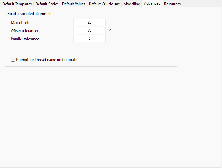
Max
Offset |
Maximum
offset for associating alignments to road strings |
Offset
tolerance |
A
percentage tolerance for the offset. If set
to 100%, the entirety of each alignment must be fully
contained inside the Max offset in order
to be associated to a road string. |
Parallel
tolerance |
A
value, in degrees, to decide whether an alignment that
is associated to a road should (by default) be treated
as a code control on the associated Road String or as
a separate String (with it's own cross section sampling
and cross sections) |
Prompt for Thread Name on Computer |
When Project Assist is run it creates a Thread including all
operations undertaken by Project Assist. If this is ticked
on the user is prompted to name the new Thread. |
|
Resources
Tab |
|
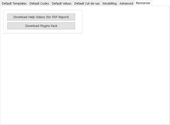
Download
Video Files |
The
output .pdf documenting all the steps Project Assist has
taken includes links to video files. These
are not installed with the sofware installation, to keep installation
size down, and can be downloaded by clicking on this button |
Download
Plugins Pack |
As
plugins (special functionality operations) are created
they will be included here for download.
Examples of plugins includes the Model Trim plugin that
installs with Civil Site Design and enables intelligent
application of a boundary to the selected design surface
model. |
|
Apply |
Apply
the changes and exit |
Set Settings as Default |
Tick to
set the current settings to be the default for future projects. |
Cancel |
Exit
the form without applying changes |


