Pipe Draw Settings
Icon:
![]()
Menu: Pipes > Settings > Pipe Draw Settings
Ribbon: Pipes Tab > Settings Panel Flyout > Pipe Draw Settings
Introduction
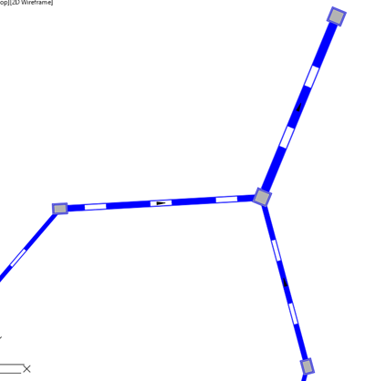
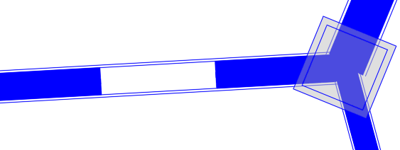
Users are able to enhance the pipe drafting in the drawing, to display polylines for the centreline, inside diameter and outside diameter, including polyline widths for each and with polyline linetypes applied.
This command sets up the drafting in the drawing for each pipe class, for the current drawing project. To establish linework drafting controls to apply to future projects, use the
![]() Global Drawing Settings command.
Global Drawing Settings command.
Drafting is only applied if toggled on for display in the ![]() Active Network Settings. This is set in the Drainage > Display tab - toggle on the toggle Use polyline specifications on a class basis to display the pipe drafting.
Active Network Settings. This is set in the Drainage > Display tab - toggle on the toggle Use polyline specifications on a class basis to display the pipe drafting.
Once toggled on to display, pipes will be drawn as per the settings in this command.
Use the command Redraw Network to update the linework when the pipe sizes are changed.
Example Outputs
In the form, the image on the far right will adjust to highlight particular controls on the form and indicate the effect of the various inputs.
Users are able to type in a layer name to be created and applied to the pipe drafting. Separate layers can be set for the centreline, inner and outer diamater lines.
Details
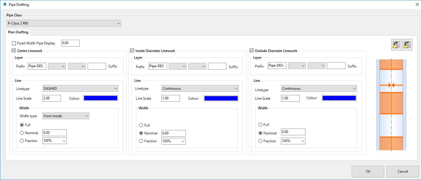
Upon selecting the command the following form is displayed:
|
|
|
|
Pipe Class |
Pick a pipe class to apply drafting linework. This is a list of pipe classes create in the Active Network Settings |
|
Plan Drafting |
Establish drafting linework for the selected pipe class. |
|
Fixed Width Pipe Display |
Toggle on to disable drafting inside and outside diameter offset polylines using the defined pipe geometry (outer diamater and inner diameter values). When toggled on, all drafted lines use the typed in width value regardless of the specified diameters. |
|
Width Value |
Type in the fixed width for display of the centreline width, inner and outer diameter lines |
|
Centre Lineworks |
Toggle this on to display polyline/s relative to the pipe centreline |
|
Layer |
Create a layer to use |
|
Layer Prefix |
Type in to create a layer name. Input here to set a layer name prefix. |
|
Pick List |
Pick to include a pipe property in the Layer name. Options are <none>,Class or Network. |
|
Pick List |
Pick to include a pipe property in the Layer name. Options are <none>,Class or Network. |
|
Layer Suffix |
Type in to create a layer name. Input here to set the layer name suffix. |
|
Line |
Line creation controls |
|
Linetype |
Pick list to select the linetype to apply from the drawing |
|
Line Scale |
Type in a value for the linetype scale |
| Colour | Click on the colour swatch to select a layer.
Select Bylayer to create Pipes on the drawing layer. |
|
Width |
Sets up whether to display a width for the centreline polyline/s. |
| Width Type | For the centreline, the Width can be drawn: - Middle. This sets for any width settings to apply from the centreline outwards - From Inside. This sets for two polylines to be drawn, with Width measured from the Inside Diameter offset toward the centreline - From Outside. This sets for two polylines to be drawn, with Width measured from the Outer Diameter offset toward the centreline |
| Toggle Options | |
| Full | Draws a polyline with a width based on the Width Type - Middle. A single polyline is drawn along the centreline with a width matching the Outer diameter - From Inside. Two polylines are drawn with widths set from the edge of the inside diameter to the centreline, one each side of the pipe centreline - From Outside. Two polylines are drawing with widths set from the edge of the outside diameter to the centreline, one each side of the pipe centreline. |
| Nominal | Draws polyline/s with a nominal width, as set by typing in a value. Width is drawn as follows: - Middle. A single polyline is drawn along the centreline at the nominal width - From Inside. Two polylines are drawn with nominal widths, from the edge of the inside diameter toward the centreline - From Outside. Two polylines are drawing with nominal widths, from the outside diameter to the centreline, one each side of the pipe centreline. |
| Fraction | Draws polyline/s with a width based on a percentage value, as set by picking values in a pick box ranging from 0% to 100%. Width is drawn as follows: - Middle. A single polyline is drawn along the centreline with the width taking up a percentage of the pipe inner diameter. - From Inside. Two polylines are drawn with a % width applied, from the edge of the inside diameter toward the centreline. 100% sets the width from the inside diamter to the centreline, both sides of the pipe centreline - From Outside. Two polylines are drawn with a % width applied, from the edge of the outside diameter toward the centreline. 100% sets the width from the outside diamter to the centreline, both sides of the pipe centreline |
|
Inside Diameter Linework |
Toggle this on to display polylines, measured from the inside diameter. |
|
Layer |
Create a layer to use |
|
Layer Prefix |
Type in to create a layer name. Input here to set a layer name prefix. |
|
Pick List |
Pick to include a pipe property in the Layer name. Options are <none>,Class or Network. |
|
Pick List |
Pick to include a pipe property in the Layer name. Options are <none>,Class or Network. |
|
Layer Suffix |
Type in to create a layer name. Input here to set the layer name suffix. |
|
Line |
Line creation controls |
|
Linetype |
Pick list to select the linetype to apply from the drawing |
|
Line Scale |
Type in a value for the linetype scale |
| Colour | Click on the colour swatch to select a layer. Bylayer and Byblock cannot be selected |
|
Width |
Sets up whether to display a width for the inside diameter polylines. |
| Toggle Options | |
| Full | Draws a polyline both sides of the pipe, with the width set to match the pipe wall (between inner diameter and outer diameter offsets. |
| Nominal | Draws polylines with a nominal width, as set by typing in a value. Type zero to have a zero width polyline. Width is drawn with the inside edge at the inner diameter offset. Width is displayed outwards from the pipe centreline |
| Fraction | Draws polylines with a width based on a percentage value, as set by picking values in a pick box ranging from 0% to 100%. Percentage width is measured between the inner diameter and outer diameter offsets. 100% sets the width to match the pipe wall (between inner diameter and outer diameter offsets) |
|
Outside Diameter Linework |
Toggle this on to display polylines, measured from the outside diameter. |
|
Layer |
Create a layer to use |
|
Layer Prefix |
Type in to create a layer name. Input here to set a layer name prefix. |
|
Pick List |
Pick to include a pipe property in the Layer name. Options are <none>,Class or Network. |
|
Pick List |
Pick to include a pipe property in the Layer name. Options are <none>,Class or Network. |
|
Layer Suffix |
Type in to create a layer name. Input here to set the layer name suffix. |
|
Line |
Line creation controls |
|
Linetype |
Pick list to select the linetype to apply from the drawing |
|
Line Scale |
Type in a value for the linetype scale |
| Colour | Click on the colour swatch to select a layer. Bylayer and Byblock cannot be selected |
|
Width |
Sets up whether to display a width for the outside diameter polylines. |
| Toggle Options | |
| Full | Draws a polyline both sides of the pipe, with the width set to match the pipe wall (between outer diameter and inner diameter offsets. |
| Nominal | Draws polylines with a nominal width, as set by typing in a value. Type zero to have a zero width polyline. Width is drawn with the outside edge at the outer diameter offset. Width is displayed inwards from the pipe centreline |
| Fraction | Draws polylines with a width based on a percentage value, as set by picking values in a pick box ranging from 0% to 100%. Percentage width is measured between the outer diameter and inner diameter offsets. 100% sets the width to match the pipe wall (between outer diameter and inner diameter offsets) |
| Export | Click to export the pipe linework settings to file. |
| Import | Click to select a saved pipe linework settings file to apply to the currently selected pipe class |
| Dynamic Display | Dynamic display window indicating effect of different inputs |
| OK | Save and exit |
| Cancel | Exit without applying changes |