Edit Structure Properties
| Icon: |
|
| Menu: | Pipes > Edit > Edit Strucutre Properties |
| Ribbon: | Pipes Tab > Edit Panel > Edit Structure Dropdown > Edit Structure |
Introduction
This command provides a way to edit the properties of a structure.
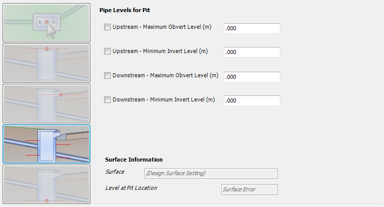
These properties include Structure Classification, Selected Road, Structure Location, Top of Structure Level, Hydraulic Design Level, Pipe Levels for Structure and Bottom of Structure Level.
Details
Upon selecting this command, at the Command prompt the user will be asked to "Locate Structure to Edit".
When a structure is selected, a glyph will appear at the structure and the following form is displayed (unless disabled in the Active Network Settings). Should a point be picked not within a specified range, a warning message will be displayed and press OK to continue and select a point closer to the require structure.
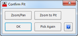 |
|
Zoom/Pan |
Provides a way to zoom or pan around in the drawing. Use Mouse Wheel to Zoom/Pan. Press Enter/Esc to Finish. |
Zoom to Structure |
Will zoom to the selected structure, so that it fits within the screen. |
OK |
Select OK to continue. |
Pick Again |
Provides the option to select a different structure, if the highlighted structure is incorrect. |
After a structure is selected the following form is displayed (the controls may vary pending the options selected):
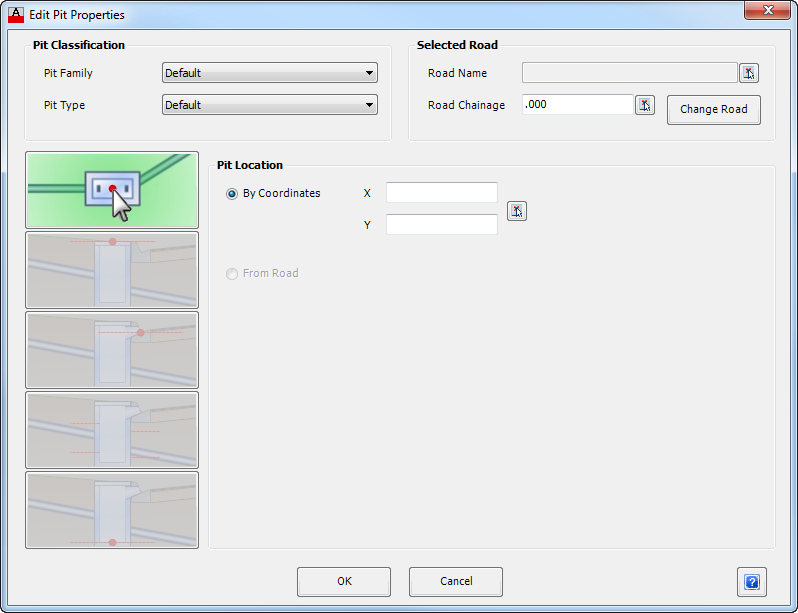 The general controls of the form are as follows: |
|
| Structure Classification | This panel is where the Family and Type of Structure can be changed. |
| Structure Family | A drop down box provides a list of all available Structure Families which can be selected. Select the appropriate Family. |
| Structure Type | A drop down box provides a list of available Structure Type from the Structure Family selected above. Select the appropriate Structure Type. Note: The user can create Structure Families and Structure Type for a specific project. These are defined in CSD Pipes > Settings > Active Network Settings. |
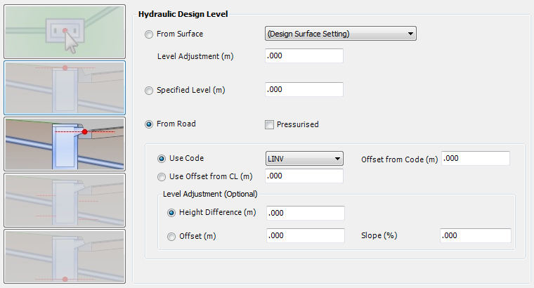
| Selected Road | This panel provides information on the relationship between the structure and a road. A different road can also be selected. |
| Road Name | Displays the Road Name to provide a relative chainage reference. The selected Road Name enables the software to extract other relevant information that is needed for calculation and reporting purposes. Use  to select the Road Alignment directly from the drawing. to select the Road Alignment directly from the drawing. |
| Road Chainage | Displays the Road Chainage for the selected Road Name, taken perpendicular to the centreline. The chainage can be entered directly into the box provided or use to select the Road Chainage directly from the drawing. |
| Change Road | This button is used to select a different Road Name for the structure to reference to. When this button is pressed a new form appears with a list of defined Roads that can be used. Caution: If this option is selected the structure location may change which will alter the defined pipe network. |
This form has five control options accessed by clicking on each of the icons represented on the left side of the form. Each selection changes the display information in the frame to the right of the icons. Control options are as follows (click on one of the links below to navigate directly to that control):
|
|
OK |
Apply and exit. |
Cancel |
Exit the form without deleting any data. |

Bottom of Structure Level |
|
 |
|
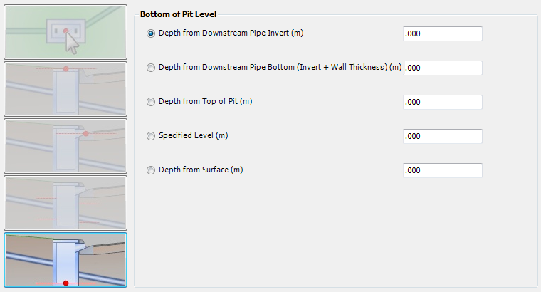
| Bottom of Structure Level | By default, the bottom of structure level is determined from the invert level of the downstream pipe. This enables full control over the Bottom of Structure Level. |
| Depth from Downstream Pipe Invert (m) | Toggle this option on to set the Bottom of Structure Level based on the Downstream Pipe Invert. Type in the additional Depth required. |
| Depth from Downstream Pipe Bottom (m) | Toggle this option on to set the Bottom of Structure Level based on the Downstream Pipe Bottom (Invert + Wall Thickness). Type in the additional Depth required. |
| Depth from Top of Structure (m) | Toggle this option on to set the Bottom of Structure Level as a fixed depth from the top of structure. Type in the depth required. This option might be used for pre-cast structures and risers. Note: this control option will not prevent the pipe levels being set below the bottom of structure levels. |
| Specified Level (m) | Toggle on this option to set a specified level for the bottom of structure. Type in the level in metres. Note: this control option will not prevent the pipe levels being set below the bottom of structure levels |
| Depth from Surface (m) | Toggle on this option to set the Bottom of Structure Level as a depth below the the Surface Level (the software uses the Design Surface as defined in the Active Network Settings). Note: this control option will not prevent the pipe levels being set below the bottom of structure levels. |