Create/Edit Drainage Catchment Area
| Icon: |
  |
| Menu: |
Pipes > Create Drainage... >
Create/Edit Drainage Catchment Area |
| Ribbon: |
Pipes Tab > Drainage Design Panel
> Catchment Area Dropdown > Catchment Area |
Introduction
This command allows for catchments created, edited and assigned to drainage
structures. Multiple catchments can be assigned to a structure.
Each catchment is described by a unique name. Once a catchment
has been defined a marker and leader is placed in the drawing and the
name is (optionally) placed beside the marker. The display
is controlled from the Active
Network Settings.
Catchments are always attached to a structure, but can be moved from
one structure to another.
Catchments are defined by areas, C factors and times of concentration. Users
are able to select the method of calculation.
Catchment Styles can be created and used to minimise and speed up data
entry.
Details
Upon selecting this command, at the Command prompt the user will
be asked to "Locate Structure Required". When
a structure is selected the following form is displayed.
|
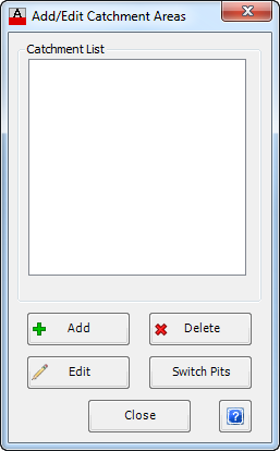
| Catchment List |
Lists catchments that are currently
attached to the selected structure. Select a catchment
to highlight it for deletion, editing or switching to another
structure. |
| Add Area |
Select this option to at a new Catchment
Area to the selected structure. There are a range of
options for defining the catchment - data inputs differ pending
the Catchment Calculation Method select, as well as how
the Area, C factor and Time of Concentration (tc) is
defined. See below for
detailed information. |
| Delete Area |
Deletes the highlighted catchment in
the list. Note: If no catchment
is selected an error message will display requesting the user
to select a catchment area. Click OK to close
the form. |
| Edit Area |
Opens the Create/Edit Catchment Areas
form for the selected catchment. Refer below
for more details. Note: If
no catchment is selected an error message will display requesting
the user to select a catchment area. Click OK
to close the form. |
| Switch Structures |
Allows the user to move the highlighted
catchment to another structure. Upon selecting this
command the user will be prompted to 'Select other structure
required'. Upon selecting the required Structure
(unless disabled in the Active
Drawing Settings), the following form is displayed.
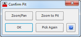
|
| Zoom/Pan |
Provides
a way to zoom or pan around in the drawing. Use
Mouse Wheel to Zoom/Pan. Press Enter/Esc to
Finish. |
| Zoom
to Structure |
Will zoom
to the selected structure, so that it fits within the
screen. |
| OK |
Select OK
to relocate the catchment to the selected structure and
return to the Add/Edit Catchment Areas form. |
| Pick
Again |
Provides
the option to select a different structure, if the highlighted
structure is incorrect. |
Note: Any drainage structure can be
selected. If no catchment is selected an error message
will display requesting the user to select a catchment area. Click
OK to close the form. |
| Close Form |
Exit this form and return to structure
selection command prompt. If no more catchment area
are to be added or edited, then press enter to exit the command. |
If a Catchment Area is not selected and either Delete Area, Edit
Area or Switch Structures is picked, a warning form will pop
up and request that a catchment area be selected. Press OK
to continue.
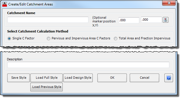
Add/Edit Catchment Area
The Create/Edit Catchment Areas form allows the user to select one of
three methods for determining the catchment calculations. Different
inputs are displayed subject to the option selected.
Note: Click on the image to jump directly
to the Catchment Calculation Method of Interest.
|
| Catchment Name |
Enter a Catchment Name. Any
standard alpha-numeric characters are permitted. If
the same catchment name is used, the software will add a suffix
number in brackets to ensure the catchment name is unique. |
| Marker Position (Optional) |
Either enter an X and Y option marker
position (real world co-ordinates) or use the pick button to select
from the drawing. This will pin the label to a fixed
location within the drawing. If the catchment area
is switched to another structure, the label will remain in its
location and the leader will stretch to the new structure. If
no offset is entered, when a structure is moved so will the label. |
| Select Catchment Calculation Method |
Three (3) options exist for the user
to input catchment areas, C factors and times of concentration. The
inputs for the mid section of the form change based on the Catchment
Calculation Method selected. |
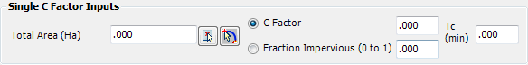
| Single
C Factor |
When this option is selected the following
information is displayed:
|
| Single
C Factor Inputs |
The options
for defining a single area catchment are: |
| Total
Area (Ha) |
Users can
type in an area, pick a polyline from the drawing or draw
a polyline for the catchment. |
 Pick Area Pick Area |
Click to
select a closed 2D polyline from the drawing. Press
[Enter] to confirm the selection and populate the Total
Area input. Note: If
a polyline is selected from the drawing the software will
maintain a link with that polyline to determine the catchment
area. Changing the polyline area will change
the catchment area. If the polyline is deleted
the software will maintain the area as a fixed value. |
 Draw Area Draw Area |
Click to
draw the area in the drawing. Click progressively
in the drawing to create the catchment segments. Press
[Enter] for the software to close the polyline and update
the Total Area input. The high and low
points will also be labelled in the drawing. Note: Layers used for the catchment
and labels is controlled from the Active
Network Settings. |
| C Factor |
Toggle on
this option to set a single C factor for the catchment. Enter
the required C factor (0-1) in the cell to the right. |
| Fraction
Impervious (0 to 1) |
Toggle on
this option to calculate the C factor based on a Fraction
Impervious. Enter a value between zero and
1. |
| Tc (min) |
Enter a
time of concentration in minutes. |
|
| Pervious
and Impervious Area C Factors |
When this option is selected the following
information is displayed:
|
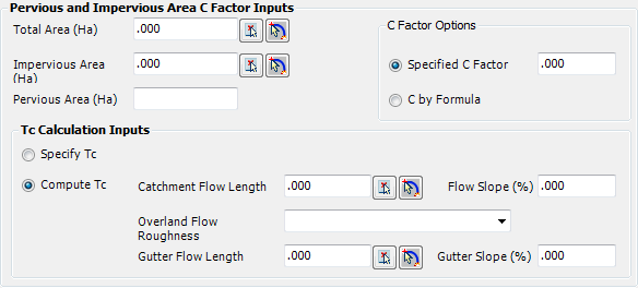
| Pervious
and Impervious Area C Factor Inputs |
Establish
the Pervious and Impervious areas, as well as the C factor
calculation method and value. |
| Total
Area (Ha) |
Users can
type in a total catchment area, pick a polyline from the
drawing or draw a polyline for the catchment. |
| Pick Area |
Click to
select a closed 2D polyline from the drawing. Press
[Enter] to confirm the selection and populate the Total
Area input. Note: If
a polyline is selected from the drawing the software will
maintain a link with that polyline to determine the catchment
area. Changing the polyline area will change
the catchment area. If the polyline is deleted
the software will maintain the area as a fixed value. |
| Draw Area |
Click to
draw the area in the drawing. Click progressively
in the drawing to create the catchment segments. Press
[Enter] for the software to close the polyline and update
the Total Area input. The high and low
points will also be labelled in the drawing. Note: Layers used for the catchment
and labels is controlled from the Active
Network Settings. |
| Impervious
Area (Ha) |
Users can
type in the impervious area of the catchment, pick a polyline
from the drawing or draw a polyline for the catchment. |
| Pick Area |
Click to
select a closed 2D polyline from the drawing. Press
[Enter] to confirm the selection and populate the Impervious
Area input. Note: If
a polyline is selected from the drawing the software will
maintain a link with that polyline to determine the catchment
area. Changing the polyline area will change
the catchment area. If the polyline is deleted
the software will maintain the area as a fixed value. |
| Draw Area |
Click to
draw the area in the drawing. Click progressively
in the drawing to create the catchment segments. Press
[Enter] for the software to close the polyline and update
the Impervious Area input. The high
and low points will also be labelled in the drawing. Note: Layers used for the catchment
and labels is controlled from the Active
Network Settings. |
| Pervious
Area (Ha) |
This is
a non-editable calculated field. Total Area
less Impervious Area. |
| C
Factor Options |
Set the
C factor using these options: |
| Specified
C Factor |
Toggle this
option to set a single C factor. Enter a value
in the cell. |
| C
by Formula |
Toggle this
option to calculate the C factor by formula. The
C factor calculation is based on Figure 1.13 of ARR. |
| Tc
Calculation Inputs |
Users select
how to determine the time of concentration (tc)
for the catchment. Two options are available: |
| Specify
Tc |
Toggle this
option on to specify a single tc value for
the catchment. Type a value in the cell (in
minutes). |
| Compute
Tc |
Toggle this
option to calculate the tc based on the catchment
flow length, roughness and gutter flow length. Inputs
are as follows:
| Catchment
Flow Length |
Enter
a value for the flow length or use the command
buttons:
- Pick Flowpath:
Select a polyline from the drawing;
-
Draw Flowpath: Click progressively in
the drawing to create the required polyline. Press
[Enter] to finish.
Note: If the Draw
Flowpath option is selected the Flow Slope
will automatically be calculated and populated. The
layer used for the catchment flow line is controlled
from the Active
Network Settings. |
| Flow
Slope (%) |
Enter
a percentage (%) value for the average slope of
the catchment. |
| Overland
Flow Roughness |
Select
a flow roughness representative of the catchment
from the list |
| Gutter
Flow Length |
Enter
a value for the flow length or use the command
buttons:
- Pick Flowpath:
Select a polyline from the drawing;
-
Draw Flowpath: Click progressively in
the drawing to create the required polyline. Press
[Enter] to finish.
Note: If the Draw
Flowpath option is selected the Flow Slope
will automatically be calculated and populated. The
layer used for the catchment flow line is controlled
from the Active
Network Settings. |
| Gutter
Slope (%) |
Enter
a percentage (%) value for the average slope of
the gutter. |
|
| Flow
Destination |
Refer separate
section below. |
|
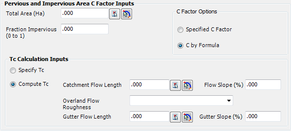
| Total
Area and Fraction Impervious |
This option includes all the function
inputs as for the Pervious and Impervious Area C Factors
(as described above) however it has a different input for calculating
the catchment areas. The area inputs are shown, below:
|
| Total
Area (Ha) |
Users can
type in an area, pick a polyline from the drawing or draw
a polyline for the catchment. |
| Pick Area |
Click to
select a closed 2D polyline from the drawing. Press
[Enter] to confirm the selection and populate the Total
Area input. Note: If
a polyline is selected from the drawing the software will
maintain a link with that polyline to determine the catchment
area. Changing the polyline area will change
the catchment area. If the polyline is deleted
the software will maintain the area as a fixed value. |
| Draw Area |
Click to
draw the area in the drawing. Click progressively
in the drawing to create the catchment segments. Press
[Enter] for the software to close the polyline and update
the Total Area input. The high and low
points will also be labelled in the drawing. Note: Layers used for the catchment
and labels is controlled from the Active
Network Settings. |
| Fraction
Impervious (0 to 1) |
Enter a
value (zero to 1) to represent the impervious area of
the catchment. |
| C
Factor Options |
Refer previous
section. |
| Tc
Calculation Inputs |
Refer previous
section. |
| Flow
Destination |
Refer separate
section below. |
All other inputs are the same as for the Pervious and Impervious
Area C Factors method. |
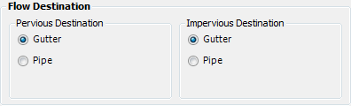
| Flow Destination |
Users select how the pervious and impervious
areas enter the structure, for all Catchment Calculation Methods
except Single C Factor:
|
| Pervious
Destination |
Select the
entry method for the pervious area of the catchment |
| Gutter |
Toggle this
option on to specify the pervious area of the catchment
to travel along the gutter to the structure. |
| Pipe |
Toggle this
option on to specify the pervious area of the catchment
to go directly into the pipe. |
| Impervious
Destination |
Select the
entry method for the impervious area of the catchment |
| Gutter |
Toggle this
option on to specify the impervious area of the catchment
to travel along the gutter to the structure. |
| Pipe |
Toggle this
option on to specify the impervious area of the catchment
to go directly into the pipe. |
|
| Description |
Add a description of the catchment if
required. Note: When Watercom
Drains is to be used, a description must be entered
here for any PAved and SUpplementary areas. A
description for GRassed is not needed. |
| Save Style |
The gives the user the ability
to save a Catchment definition for reuse within this project or
future projects. When save style is picked, the user
is required to enter an appropriate file name. |
| Load Full Style |
This is used to load in a Catchment
Style that has been saved previously. A Full Style
includes Catchment Areas, along with all other data on the form. When
this option is selected, a warning message is displayed as ALL
entered information will be overwritten. |
| Load Design Style |
This is used to load in a Catchment
Style that has been saved previously. A Design Style
includes only C Factors and Tc information. Areas and
description remain unchanged. |
| Load Previous Style |
This is used to load in the Previous
Catchment Style loaded - the style name appears to the right of
this button. |
| OK |
Create/Edit catchment and exit. |
| Cancel |
Exit the form without applying any changes. |
Note: Should any critical field
be left blank a warning message will pop up indicating what data is missing,
press OK and enter the appropriate information.