Points by Reference
Icon: |
Introduction
This command allows users to create COGO Points that reference Design objects (Alignments, Surfaces, Strings and Codes) to manage insertion positions, elevations and textual information. This command could be used for setout of point data, for example, with users electing to pickup a Code from a string for x,y,z position. Users could then create/update a Point Group and output a table of information. This could include chainage, offset, and other information related to the string.
Once created, the Update Points command can be used to update the positions of the points based on changes to the reference object data.
Reference Controls
When setting up a reference to other objects, the software uses the Positioning Form which allows for independent horizontal positioning and elevation assignment for the point. The Positioning Form enables the following controls for the point insertion and elevation:
Horizontal
Position can be by selection in the drawing, by alignment or using String codes
When an alignment or String Code/s is/are used, the Calculate Rotation can be applied to set a rotation to the inserted object
Vertical
Users can specify an elevation, reference a surface or a String (elevations interpolated between codes on the string)
Dynamic reference will ensure the object updates vertical positioning when Model Viewer is refreshed.
The horizontal position can be independently established compared with the vertical position. This allows for elevations to be relative to, say, the centreline of a road and the horizontal position to be relative to, say, the left side back of kerb.
Details
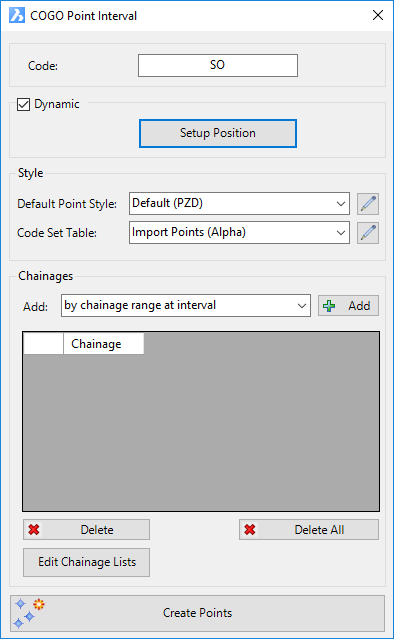
Upon selecting the command the following form is displayed:
|
|||||||||||||||||||||||||||
Code |
Type in a Description for the Points | ||||||||||||||||||||||||||
Dynamic |
Ticked on by default. This allows for the horizontal and vertical positioning of the point to be referenced to alignments, string codes or (vertically) surface. | ||||||||||||||||||||||||||
Dynamic tick |
Tick on to apply dynamic (referenced) positioning | ||||||||||||||||||||||||||
Setup Position |
This
opens the Positioning
Form for the user to establish the horizontal (x,y) insertion
and vertical (z) of the point. Below is a sample of
attaching to a String code horizontally and vertically. See
the Positioning
Form help for more information.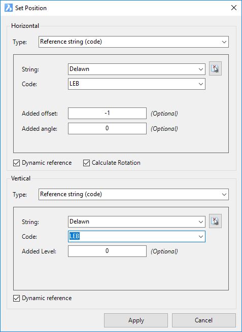 |
||||||||||||||||||||||||||
Style |
Set the Point Style to apply for the created point/s. | ||||||||||||||||||||||||||
Default Point Style |
Select a Point Style for display of the point, in the case that the point description is not found in the Code Set Table. | ||||||||||||||||||||||||||
|
Click to open the Point Style Editor to create/edit/manage Point Styles. | ||||||||||||||||||||||||||
Code Set Table |
Select a Code Set Table to apply a Point Style, Layer and Description formatting based on a matching Code. | ||||||||||||||||||||||||||
|
Click to open the Code Set Table to create/edit/manage point codes for auto assignment of styles, layers and description formatting. | ||||||||||||||||||||||||||
Chainages |
|||||||||||||||||||||||||||
Dynamic tick |
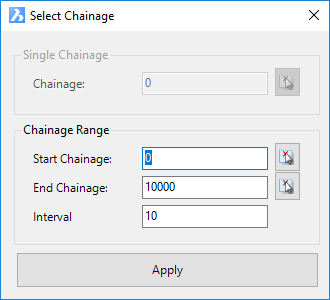
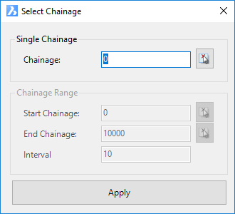
Use
the pick list to select the method for adding points at distances
along the selected alignment/string. Options are split into two
sections, separated with -----------------------------. Top
section is user input for creation. Below the dashed
line the Section
Manager lists are displayed.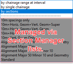 |
||||||||||||||||||||||||||
Add |
After
selecting the method of addition, clicking here will either add
the distances to the list view or open a form for setting the
outputs. Conditional checks requiring user input are
listed below:
|
||||||||||||||||||||||||||
[List of Positions] |
List of positions along the selected alignment/string (distances measured from start of the alignment/string) | ||||||||||||||||||||||||||
Delete |
Delete a selected position in the list. This will remove the point from the drawing, or prevent creation | ||||||||||||||||||||||||||
Delete All |
Delete all items in the list | ||||||||||||||||||||||||||
Edit Chainage Lists |
This opens the Section Manager form for the selected Alignment/String set up in the Setup Position form above. | ||||||||||||||||||||||||||
Create Points |
Create the points in the drawing, referenced to the selected object/s. |
||||||||||||||||||||||||||