Icon:
Icon: |
The Export Corridor command:
Gathers the Strings used in the selected Model.
Finds the Civil Site Design template Codes and cross section Codes used
Creates matching Subassemblies and Assemblies
Creates a Corridor with regions (applying the appropriate assemblies), target mapping and parameter overrides.
The Exchange Settings are critical to step 2 and 3 in the above process - it manages the correlation between the Civil Site Design Template/Codes and the Civil 3D Assembly/Subassemblies.
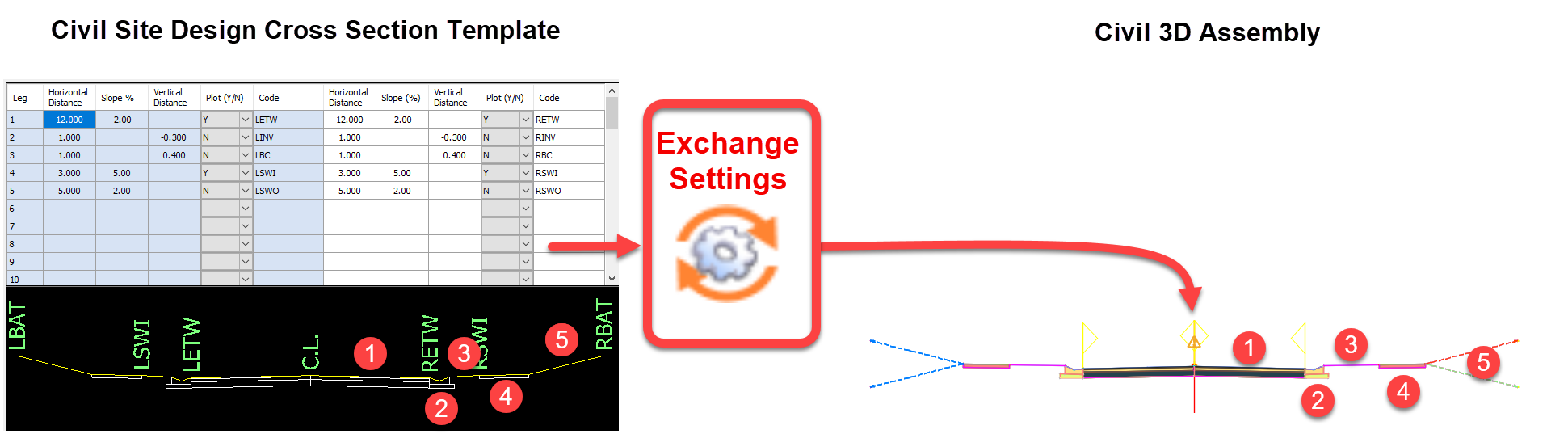
The Exchange Settings manages the creation of Civil 3D Subassemblies from the Civil Site Design cross sections. Using the Exchange Settings users can:
Create Conversion Files. These include Code Groups for selecting Code/s in Civil Site Design and assigning them to particular Civil 3D Subassemblies.
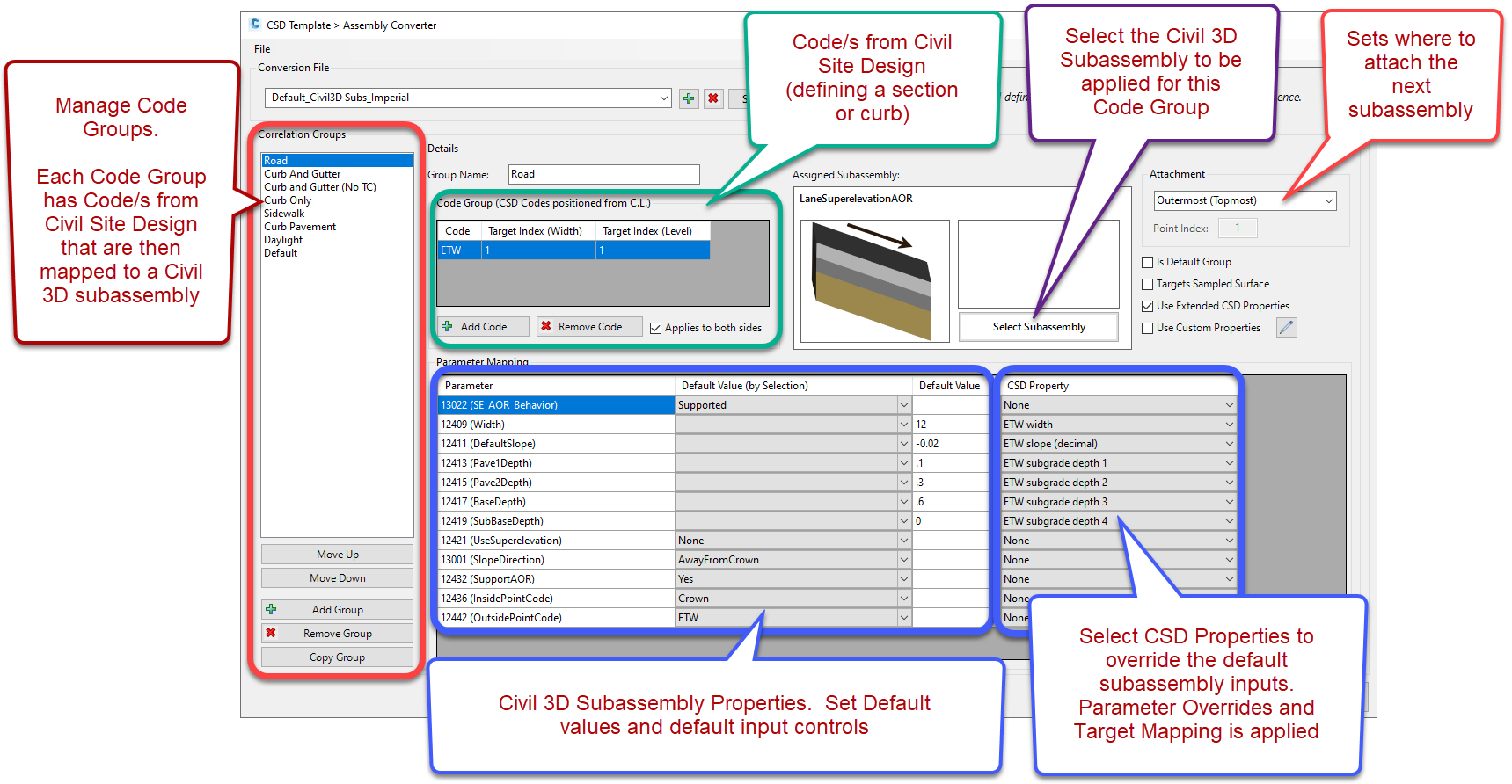
Create Code Groups. A Code Group establishes the Code (in the case of a Civil Site Design section) or Codes (in the case of a Civil Site Design Kerb Return) and Civil 3D subassembly to apply. In a Code Group users:
Add in the Civil Site Design Code/s.
Select the Civil 3D Subassembly to be used for the select Code/s
Set up the default subassembly inputs and select which inputs should be controlled by Civil Site Design (a CSD Property is assigned to control an input of the subassembly)
It is critical that each Conversion File account for every Code used in Civil Site Design. Each Code must have a subassembly assigned, otherwise a corridor will not be created. To achieve this:
Conversion Files MUST have one ‘Default’ group (this has the ‘Is Default Group’ box ticked on) to allow for unassigned codes (except for the BAT code) to have a subassembly applied
Converison Files must also have one Code Group set for the Daylight code (BAT). ‘Targets Sampled Surface’ should be ticked on for this Code Group.
If a Default Value is set for the subassembly and this matches a CSD Property value (or if no CSD Property is assigned) then there will be no overrides applied (eg: if the subassembly width is set to 12, and the CSD Property returns a value of 12, no overrides are applied to those corridor sections).
A CSD Property is a value stored by Civil Site Design. Properties include:
CSD Property inputs can be used to control subassembly inputs.
When a Conversion File is created or saved, it is stored in the CSD Settings folder (opened using the Open Setttings Folder command), in a folder named Corridor Conversion. Each file has extension .ccf.
Users are encouraged to create multiple Conversion Files to support the different assembly outputs required.
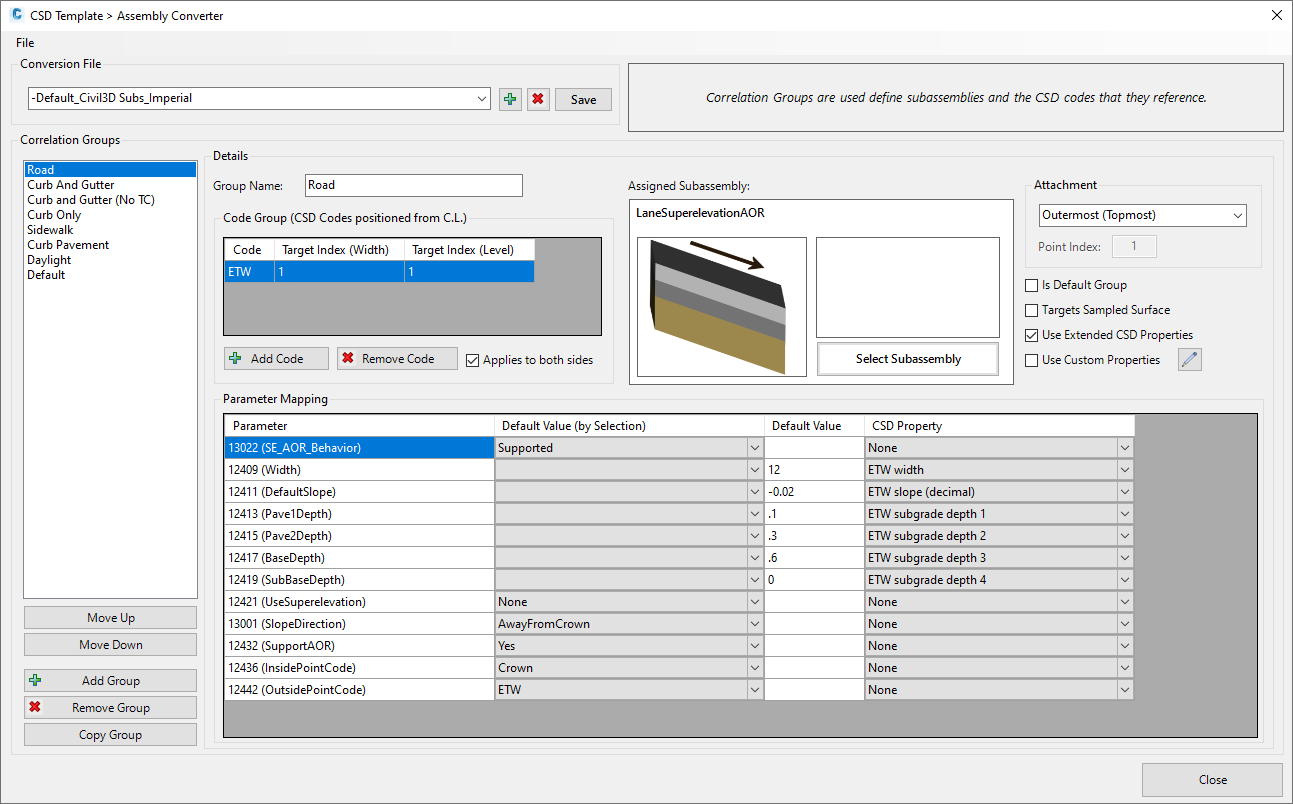
Upon selecting the command the following form is displayed:
|
|||||||||||||||||||||||||||||||||||||||||||||
File Menu |
Provides tools to manage conversion files. | ||||||||||||||||||||||||||||||||||||||||||||
New Conversion |
Click to create a new Conversion File. Provide a name for the file. | ||||||||||||||||||||||||||||||||||||||||||||
Save Conversion |
Click to save the current Conversion File. | ||||||||||||||||||||||||||||||||||||||||||||
Copy Conversion |
Click to create a copy of the current Conversion File. Input a name for the new file. | ||||||||||||||||||||||||||||||||||||||||||||
Delete Conversion |
Click to delete the current Conversion File. | ||||||||||||||||||||||||||||||||||||||||||||
Conversion File |
Select the conversion file to edit, as well as create new, delete and save | ||||||||||||||||||||||||||||||||||||||||||||
Conversion File picklist |
Select a conversion file to edit. | ||||||||||||||||||||||||||||||||||||||||||||
Add |
Click to create a new conversion file. Provide a name for the file. | ||||||||||||||||||||||||||||||||||||||||||||
Delete |
Click to delete the current conversion file. | ||||||||||||||||||||||||||||||||||||||||||||
Save |
Click to save the file (also press Ctrl+S). | ||||||||||||||||||||||||||||||||||||||||||||
Correlation Groups |
Create code groups and establish subassemblies to apply. | ||||||||||||||||||||||||||||||||||||||||||||
Correlation Group List |
List of named correlation groups. Click to make a correlation group current for editing, copy and deletion. | ||||||||||||||||||||||||||||||||||||||||||||
Move Up |
Move the selected correlation group up in the list. The software processes the correlation group from top of list to bottom. | ||||||||||||||||||||||||||||||||||||||||||||
Move Down |
Move the selected correlation group down in the list. The software processes the correlation group from top of list to bottom. | ||||||||||||||||||||||||||||||||||||||||||||
Add Group |
Create a new Correlation Group. The group will need to be named as part of the creation process. | ||||||||||||||||||||||||||||||||||||||||||||
Remove Group |
Delete the selected Correlation Group. | ||||||||||||||||||||||||||||||||||||||||||||
Copy Group |
Copy the selected Correlation Group and rename. | ||||||||||||||||||||||||||||||||||||||||||||
Group Name |
Set the name for the Correlation Group. | ||||||||||||||||||||||||||||||||||||||||||||
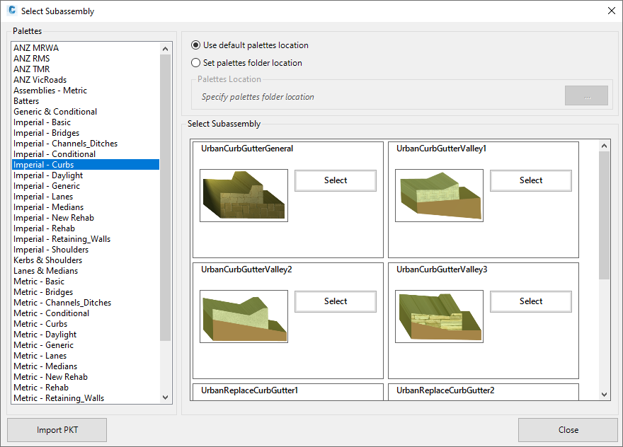
Assigned Subassembly |
Click
on Select Subassembly to select the subassembly to apply to the
group. The following form will display:
|
||||||||||||||||||||||||||||||||||||||||||||
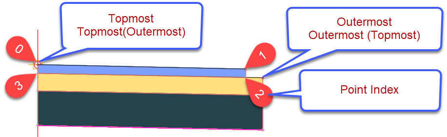
Attachment |
The software automatically 'attaches' subassemblies to each other. | ||||||||||||||||||||||||||||||||||||||||||||
Attachment Picklist |
There a number of options for determining how the next subassembly should attach to this selected subassembly:
|
||||||||||||||||||||||||||||||||||||||||||||
Point Index |
Type in a number for the Point Index. This will only apply if 'Specify Point Index' is selected in the Attachment picklist. | ||||||||||||||||||||||||||||||||||||||||||||
Is Default Group |
One
Code Group must be set as the 'Default Group'. The
Default group will be used in the event that there are Code/s
used in Civil Site Design that are not otherwise included in a
Code Group. Tick this on to set the Default Group. Note: Any Code can be added in the Code Group list when 'Is Default Group' is ticked on. The code name will be adjusted for the actual Civil Site Design Code used in design. |
||||||||||||||||||||||||||||||||||||||||||||
Targets Sampled Surface |
The daylight (batter) code (BAT Code) should be set up as a Code Group and 'Targets Sampled Surface' ticked on. | ||||||||||||||||||||||||||||||||||||||||||||
Use Extended CSD Properties |
The default CSD Properties include 4 layers. When ticked on, additional properties will be exposed (all 10 layers of Civil Site Design, inside and outside widening per pavement layer as well as inside/outside pavement layer slopes). | ||||||||||||||||||||||||||||||||||||||||||||
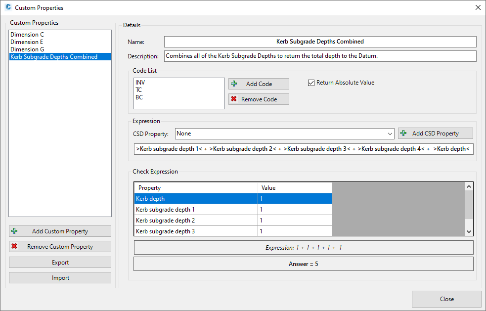
Use Custom Properties |
A number of subassembly inputs are measured differently to Civil Site Design (an example of this is the UrbanCurbGutterGeneral subassembly which only has one layer for the pavement and requires an input for the depth along the back of curb from top to base. Tick on enable Custom Properties. | ||||||||||||||||||||||||||||||||||||||||||||
|
Click
to create and edit calculations using CSD Properties. Each
Custom Property (CSD Property calculation) is created for the
selected Correlation Group only. Use Export and Import
on this form to share them out to file and to another Correlation
Group. The following form will display:
|
||||||||||||||||||||||||||||||||||||||||||||
Code Group |
Set the Civil Site Design Code/s to search for to assign the subassembly and apply CSD Properties. | ||||||||||||||||||||||||||||||||||||||||||||
Code Group List |
List
of Code/s to use for matching a Civil 3D Subassembly. Table
includes:
|
||||||||||||||||||||||||||||||||||||||||||||
Add Code |
Click to input a new Code to add to the Code Group list. | ||||||||||||||||||||||||||||||||||||||||||||
Remove Code |
Remove the highlighted code from the Code Group list. | ||||||||||||||||||||||||||||||||||||||||||||
Applies to Both Sides |
Toggle this on for the same assembly to be applied left and right of the string centreline (eg: LETW and RETW are treated with the same subassembly). If ticked on, OMIT the prefix L and R normally applied to the Civil Site Design codes. | ||||||||||||||||||||||||||||||||||||||||||||
Parameter Mapping |
Set the default values to apply to each of the subassembly inputs as well as allow override control by Civil Site Design | ||||||||||||||||||||||||||||||||||||||||||||
Parameter |
The list of items here depends on the subassembly selected. Each user input for the subassembly is listed under this column. | ||||||||||||||||||||||||||||||||||||||||||||
Defaut Value (by Selection) |
If the input is a picklist item, it will be listed here. Users can set a Default behaviour to apply when the subassembly is created. CSD Properties cannot be applied to picklist values. | ||||||||||||||||||||||||||||||||||||||||||||
Defaut Value |
If the input is a user input (numeric or alphanumeric, it will be listed here. Users can set a Default Value to apply when the subassembly is created. | ||||||||||||||||||||||||||||||||||||||||||||
CSD Property |
A CSD Property is a variable from Civil Site Design that is stored and available for use in assigning a value to a subassembly. Pick a CSD Property to assign to the subassembly input. | ||||||||||||||||||||||||||||||||||||||||||||
Close |
Close the form. If there are unsaved edits, a form will display to save the Conversion File before exiting the form. | ||||||||||||||||||||||||||||||||||||||||||||