Create/Edit Knuckle
| Icon: |
|
Introduction
The Create/Edit Knuckles command is a powerful routine to automate the creation of localised road widenings, including the following processes:
- Create New
- Use simple parametric inputs to generate/update an alignment for the knuckle, including match in to the edge of the roadway to which it connects
- Assign a cross section (Template) as part of the vertical design
- Assign vertical controls to 'read in' the road levels and apply them to parts of the knuckle
- Generate a profile that is automatically and continuously matched to the shape and levels of the Road to which it connects
- Edit Existing
- Adjust horizontal inputs to update the knuckle alignment, whilst maintaining connectivity to the Road
- Edit the connecting road and the extent of automatic profile matching to the connecting Road
Once created the Knuckle profile can be edited immediately via the ![]() Vertical Grading Editor, and users can make additional edits to the knuckle profile via the
Vertical Grading Editor, and users can make additional edits to the knuckle profile via the ![]() Create/Edit Roads command.
Create/Edit Roads command.
Main Processes
The main process for creating/editing a knuckle is as follows:
- Establish the knuckle name, definition and connectivity
- Set the knuckle horizontal geometry parameters
- Create/Update the knuckle (alignment) geometry
- Set profile controls for the knuckle interaction with the adjacent Road
Form Interface
The form is separated into three parts:
- Left side. This is the inputs area
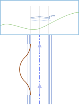
- Right top section. This is a dynamic graphics window (and text box) which will update as the user hovers over each input. It provides a visual description of what the input means
- Right Bottom section. Create the alignment and string for the knuckle.
Details
This command can be used to Create as well as Edit a knuckle. The form suppresses some functionality in the edit mode.
| Special Notes: | Designers must first create the Road to which the knuckle is connected. Use the |
|
If a user alignment is specified, it is recommended to create this in the same
direction as the Road String to which it is being connected. |
Creating a Knuckle - Starting the Command
Upon starting the command the command prompt reads:
Select knuckle to edit [Enter if creating a new knuckle alignment]
Options are:
- Creating a NEW knuckle: Press the [Enter] button on the keyboard
- Editing an existing knuckle: click on or near to the alignment in the drawing
Display Components
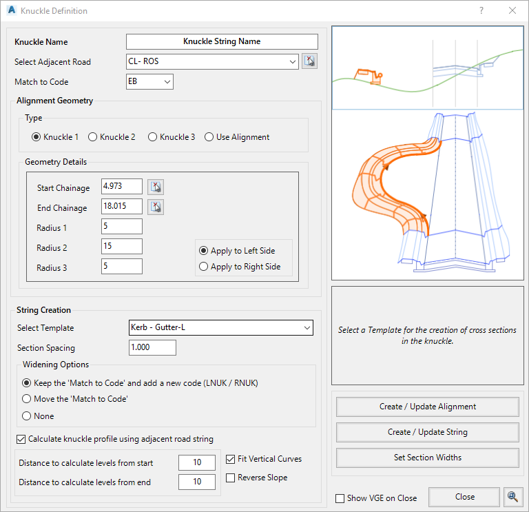
Once the alignment is selected or the [Enter] button is pressed, the following form is displayed:
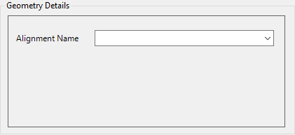
| Knuckle Name |
This is the name that will be assigned to the new knuckle object created in
Civil Site Design, as well as the name of the Alignment that will be created. Note: This field will be non-editable when editing a created Knuckle alignment/string. |
||||||||||||||||||||||
| Select Adjacent Road | Use the pick list to select a Road for the knuckle to connect to. | ||||||||||||||||||||||
| Match to Code |
Civil Site Design automates the horizontal alignment creation of the knuckles
(except for Use Alignment) by locating a particular Code from the Road on either the left or right side. This Code normally defines the edge of the roadway, and sets where the knuckle alignment should connect.
Use the pick list to select the appropriate Code from the incoming Road cross section. |
||||||||||||||||||||||
|
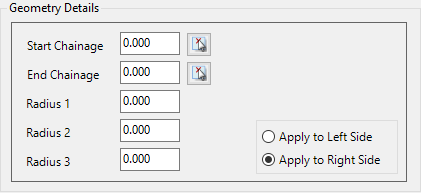
Alignment Geometry |
Establish the alignment geometry for the knuckle | ||||||||||||||||||||||
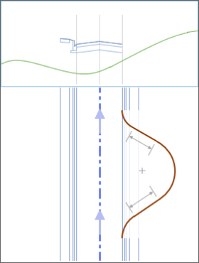
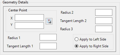
|
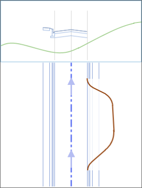
Type: Knuckle 1 |
|
||||||||||||||||||||||
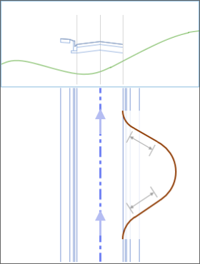
|
Type: Knuckle 2 |
|
||||||||||||||||||||||
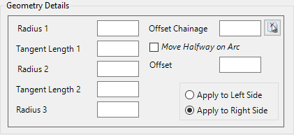
|
Type: Knuckle 3 |
|
||||||||||||||||||||||
|
Type: Use Alignment |
|
||||||||||||||||||||||
|
String Creation |
After the Alignment has been created (after pressing the Create/Update Alignment button on this form) users can establish controls for turning the Knuckle alignment into a String | ||||||||||||||||||||||
|
Section Template |
Use the pick list to select a Template for the creation of cross sections in the knuckle. | ||||||||||||||||||||||
|
Section Spacing |
Type in a value for the spacing between calculated cross sections for the knucle string | ||||||||||||||||||||||
| Widening Options | Establish controls for how the Knuckle String is used to control the Adjacent Road cross sections | ||||||||||||||||||||||
| Keep the 'Match to Code' and add a new Code (LNUK/RNUK)xc |
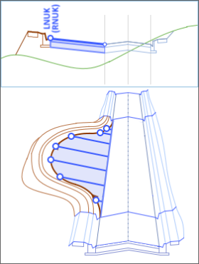 Over the chainage range of the knuckle, removes all Codes of the Adjacent Road from the 'Match to Code' outwards. Creates a code (LNUK/RNUK pending the side of the Adjacent Road) and automatically connects this code to the Knuckle String centreline. Note: If the subgrade for the road does not display correctly, then the designer may have use the "Subgrade by Labels" option on the template editor. The automatic label that is created is LNUK or RNUK (depending on which side of the road the knuckle is located). For more information click here. |
||||||||||||||||||||||
| Set 'Match to Coode' to use Knuckle Vertical Design |
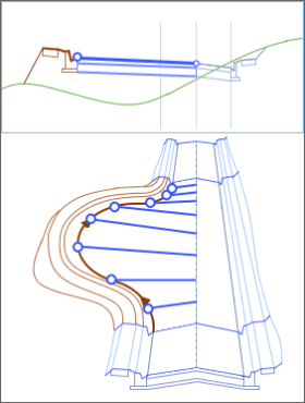 Over the chainage range of the knuckle, removes all Codes of the Adjacent Road from the 'Match to Code' outwards. The 'Match to Code' on the Adjacent Road automatically connects to the Knuckle String centreline. |
||||||||||||||||||||||
| None |
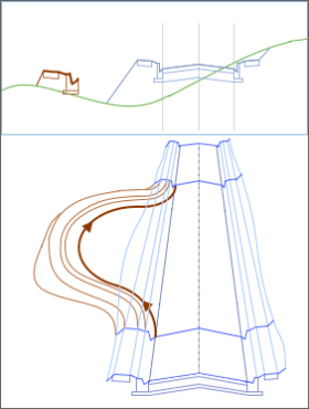 The Adjacent Road will not be adjusted to accommodate the knuckle. Users can then manually establish how the Adjacent Road should adjust (if at all) for the Knuckle inclusion. |
||||||||||||||||||||||
| Calculate Knuckle Profile | Automate the vertical design of the knuckle (beyond the start/end connection elevations being set by the Adjacent Road 'Match to Code' elevations | ||||||||||||||||||||||
|
Tick Box: Calculate knuckle profile using adjacent road string |
If ticked on, vertical IP's can be automatically created on the Knuckle String (at the selected Section Spacing) to adopt elevations referenced to the Adjacent Road string). | ||||||||||||||||||||||
|
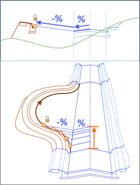
Distance to calculate levels from start |
A distance, measured along the Adjacent Road from the Start position on the Adjacent Road, to automatically insert vertical IP's on the knuckle string. Elevations will be calculated by projecting the crossfall of the Adjacent Road 'Match to Code' out to the Knuckle offset (users can elect to transfer the same crossfall or reverse crossfall to the Knuckle string) | ||||||||||||||||||||||
|
Distance to calculate levels from end |
A distance, measured along the Adjacent Road from the End position on the Adjacent Road, to automatically insert vertical IP's on the knuckle string. Elevations will be calculated by projecting the crossfall of the Adjacent Road 'Match to Code' out to the Knuckle offset (users can elect to transfer the same crossfall or reverse crossfall to the Knuckle string) | ||||||||||||||||||||||
|
Fit Vertical Curves |
Tick on to automatically design the vertical design of the
knuckle between the automatically inserted vertical IP's.
This will insert either 1 vertical curve that matches the
incoming/outgoing grades for the full length between the
vertical IP's, or two equal length vertical curves adopting
the incoming/outgoing grades with total length measuring the
full length between the vertical IP's. Untick to adopt a single tangent between the automatically inserted vertical IP's. |
||||||||||||||||||||||
|
Reverse Slope |
Applies to the 'Distance to calculate levels' inputs. Tick on to use the elevations of the 'Match to Code' on the Adjacent Road and apply the REVERSE crossfall calculated to the 'Match to Code' (if the crossfall to the 'Match to Code' is -3%, then a +3% crossfall would be used to calculate elevations for vertical IP's on the Knuckle String Tick off to use the elevations of the 'Match to Code' on the Adjacent Road and apply the same crossfall calculated to the 'Match to Code' (if the crossfall to the 'Match to Code' is -3%, then a -3% crossfall would be used to calculate elevations for vertical IP's on the Knuckle String |
||||||||||||||||||||||
| Hover Image |
 This window will update based on the hover location of the mouse on the form. |
||||||||||||||||||||||
| Help Text Box | Provides information about the option under the mouse hover position. | ||||||||||||||||||||||
| Create/Update Alignment |
Click to generate an Alignment for the Knuckle based on the displayed Knuckle design parameters and connection details defined at the top of the form. This will create an Alignment connected to the selected Road at the specified connection point at the start and end of the Knuckle alignment
(for Use Alignment, the designer is required to ensure connection of the
alignment start/end to the Match Code).
Note: The initial display and label style applied (when the alignment is created) is set from the
If the geometry does not enable creation of a knuckle alignment an error message will display. If the alignment is not appearing as desired, simply change the parameters defining the horizontal geometry and click on the Create/Update Alignment button again to recreate the alignment. |
||||||||||||||||||||||
| Create/Update String | Creates/Updates the Knuckle String. The string will be created, the Adjacent Road edited as per the Widening options and, if created, the Auto Model (TotalModel) surface will be updated. | ||||||||||||||||||||||
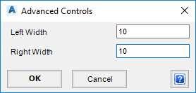
| Set Section Widths |
|
||||||||||||||||||||||
| Show VGE on Close | If ticked on, when the form is closed the Vertical Grading Editor for the Knuckle String will open, allowing for redesign vertically and adjustments to cross sections. | ||||||||||||||||||||||
| Close | Click to close the form. | ||||||||||||||||||||||
| Zoom/Pan | Click to allow zoom/pan in the drawing using the middle mouse button. Press [enter], [esc] or left click the mouse button to return to the form. | ||||||||||||||||||||||
 icon to select the location from the screen