Label Settings
Icon: ![]()
![]()
Menu: Alignments > Settings > Label Settings
Ribbon: Alignments Tab > Settings Panel > Label Settings
Introduction
The Label Settings (also known as the Annotation Settings) command provides user control over all the different types of annotations (labels) that can be applied along the alignment. The Label Settings form provides a management framework for textual display controls on alignments.
There are two levels of annotations (labels) for alignments:
- Annotation Styles: these describe different ways to display chainage information at a location on an alignment
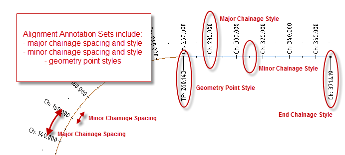
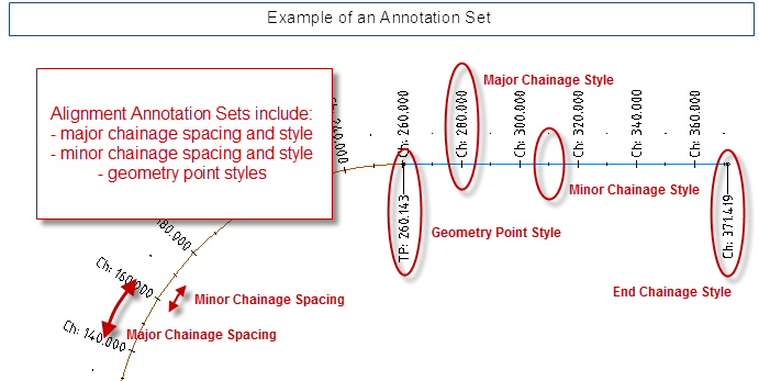
- Alignment Annotation Sets (aka Alignment Label Sets): these describe how Annotation Styles should be applied along an entire alignment - it sets out, for example, the spacing between major and minor chainages as well as the way minor and major and geometry chainages should display. Annotation Sets reference Annotation Styles.
An Alignment Annotation Set can be loaded for any alignment to pre-set the display output. Users can manually adjust the major and minor chainage spacings and the Annotation Styles applied to any particular alignment.
Individual Alignment Annotations in the drawing can be moved using AutoCAD grips - once this occurs the annotation/label will go into the Dragged State. Users can set different display characteristics in the Dragged State condition.
Note: When an alignment is created, it applies the Alignment Annotation Set selected in the Active Drawing Settings > Styles tab.
Details
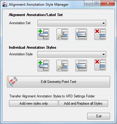
Upon selecting the command the following form is displayed:
 |
||||||||||||||||||||||||||||||||||||||||||||||||||||||||||||||||||||||||||||||||||||||||||||||||||||||||||||||||||||||||||||||||||||||||||||||||||||||||||||||
| Alignment Annotation/Label Set | Allows the user to manage Annotation Sets - create, delete, copy and edit Annotation Sets from here | |||||||||||||||||||||||||||||||||||||||||||||||||||||||||||||||||||||||||||||||||||||||||||||||||||||||||||||||||||||||||||||||||||||||||||||||||||||||||||||
| Annotation Set pick list | Select an Annotation Set for editing, copying or deletion | |||||||||||||||||||||||||||||||||||||||||||||||||||||||||||||||||||||||||||||||||||||||||||||||||||||||||||||||||||||||||||||||||||||||||||||||||||||||||||||
| |
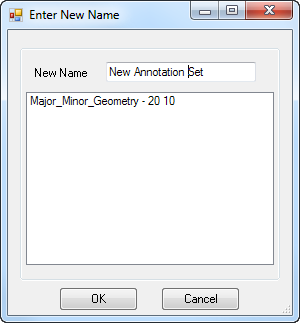
Click to create a new Annotation Set. The following form is displayed:
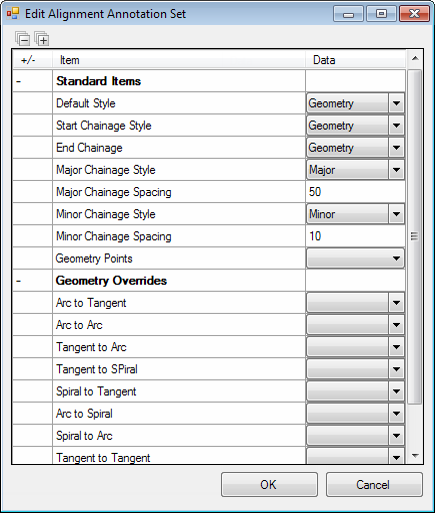
After entering a new name the following form is displayed:
|
|||||||||||||||||||||||||||||||||||||||||||||||||||||||||||||||||||||||||||||||||||||||||||||||||||||||||||||||||||||||||||||||||||||||||||||||||||||||||||||
| |
Click to edit the currently selected Annotation Set.
Controls to edit the Annotation Set will be the same as for Add New, above. |
|||||||||||||||||||||||||||||||||||||||||||||||||||||||||||||||||||||||||||||||||||||||||||||||||||||||||||||||||||||||||||||||||||||||||||||||||||||||||||||
| |
Click to copy the currently selected Annotation Set. Input controls are exactly the same as for the Add New command. | |||||||||||||||||||||||||||||||||||||||||||||||||||||||||||||||||||||||||||||||||||||||||||||||||||||||||||||||||||||||||||||||||||||||||||||||||||||||||||||
| |
Click to delete the currently selected Annotation Set - a message will display for the user to confirm deletion. | |||||||||||||||||||||||||||||||||||||||||||||||||||||||||||||||||||||||||||||||||||||||||||||||||||||||||||||||||||||||||||||||||||||||||||||||||||||||||||||
| Individual Annotation Styles | Allows the user to manage Annotation Styles - create, delete, copy and edit Annotation Sets from here | |||||||||||||||||||||||||||||||||||||||||||||||||||||||||||||||||||||||||||||||||||||||||||||||||||||||||||||||||||||||||||||||||||||||||||||||||||||||||||||
| Annotation Style pick list | Select an Annotation Style for editing, copying or deletion | |||||||||||||||||||||||||||||||||||||||||||||||||||||||||||||||||||||||||||||||||||||||||||||||||||||||||||||||||||||||||||||||||||||||||||||||||||||||||||||
| |
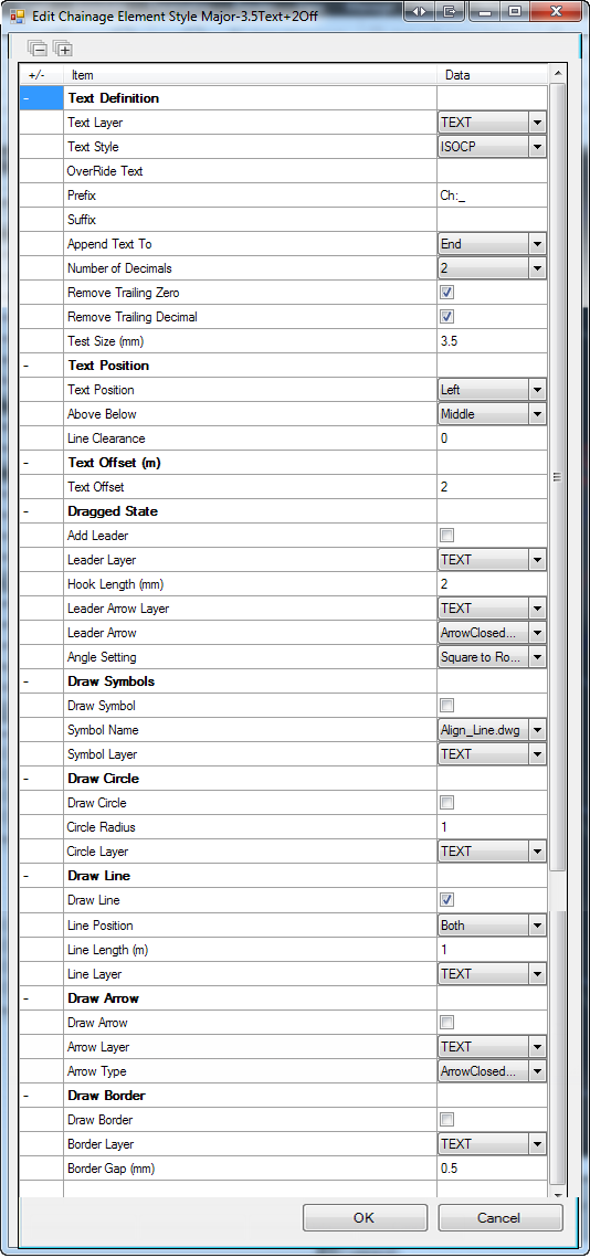
Click to create a new Annotation Style. The following form is displayed:
After entering a new name the following form is displayed:
|
|||||||||||||||||||||||||||||||||||||||||||||||||||||||||||||||||||||||||||||||||||||||||||||||||||||||||||||||||||||||||||||||||||||||||||||||||||||||||||||
| |
Click to edit the currently selected Annotation Style.
Controls to edit the Annotation Set will be the same as for Add New Style, above. |
|||||||||||||||||||||||||||||||||||||||||||||||||||||||||||||||||||||||||||||||||||||||||||||||||||||||||||||||||||||||||||||||||||||||||||||||||||||||||||||
| |
Click to copy the currently selected Annotation Style. Input controls are exactly the same as for the Add New Style command. | |||||||||||||||||||||||||||||||||||||||||||||||||||||||||||||||||||||||||||||||||||||||||||||||||||||||||||||||||||||||||||||||||||||||||||||||||||||||||||||
| |
Click to delete the currently selected Annotation Style - a message will display for the user to confirm deletion. | |||||||||||||||||||||||||||||||||||||||||||||||||||||||||||||||||||||||||||||||||||||||||||||||||||||||||||||||||||||||||||||||||||||||||||||||||||||||||||||
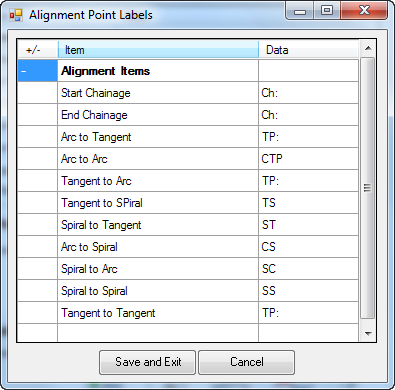
This allows the user to type in Geometry Point text that can be applied to the geometry point Annotation styles along the alignment. After clicking on this button the following form is displayed:
|
||||||||||||||||||||||||||||||||||||||||||||||||||||||||||||||||||||||||||||||||||||||||||||||||||||||||||||||||||||||||||||||||||||||||||||||||||||||||||||||
| Transfer Alignment Annotation Styles to CSD Settings Folder | Styles created in the Label Settings form are, by default, only saved to the current project. These command buttons allow the user to pass the local settings across to the CSD Settings folder so the settings will be available in future projects. | |||||||||||||||||||||||||||||||||||||||||||||||||||||||||||||||||||||||||||||||||||||||||||||||||||||||||||||||||||||||||||||||||||||||||||||||||||||||||||||
| Add New Styles Only | Click this button to add any new Annotation Sets and Annotation Styles to the CSD Settings folder. This occurs immediately upon pressing the button and with no confirmation message. | |||||||||||||||||||||||||||||||||||||||||||||||||||||||||||||||||||||||||||||||||||||||||||||||||||||||||||||||||||||||||||||||||||||||||||||||||||||||||||||
| Add and Replace All Styles | Click this button to add ALL the Annotation Sets and Annotation Styles to the CSD Settings folder. Existing Annotation Sets and Annotation Styles in the CSD Settings will be replaced with any from the local project. This occurs immediately upon pressing the button and with no confirmation message. | |||||||||||||||||||||||||||||||||||||||||||||||||||||||||||||||||||||||||||||||||||||||||||||||||||||||||||||||||||||||||||||||||||||||||||||||||||||||||||||
| Exit | Close the form. | |||||||||||||||||||||||||||||||||||||||||||||||||||||||||||||||||||||||||||||||||||||||||||||||||||||||||||||||||||||||||||||||||||||||||||||||||||||||||||||

