LandXML Transfer
Icon: 
Menu: Alignments > LandXML Transfer
Ribbon: Alignments Tab > Design Panel > Alignment LandXML Transfer
Introduction
Use this command to create alignments in the software from a LandXML file, and to export alignment data out into a LandXML file for use in alternate design packages such as AutoCAD Civil 3D.
Traditionally this command is used to share alignment data with alternate design packages such as AutoCAD Civil 3D.
If designers are porting data between CSD on the AutoCAD platform and CSD on the AutoCAD Civil 3D platform, use LandXML to share surface and alignment data across the platforms.
Details
Upon selecting the command the following form is displayed:
|
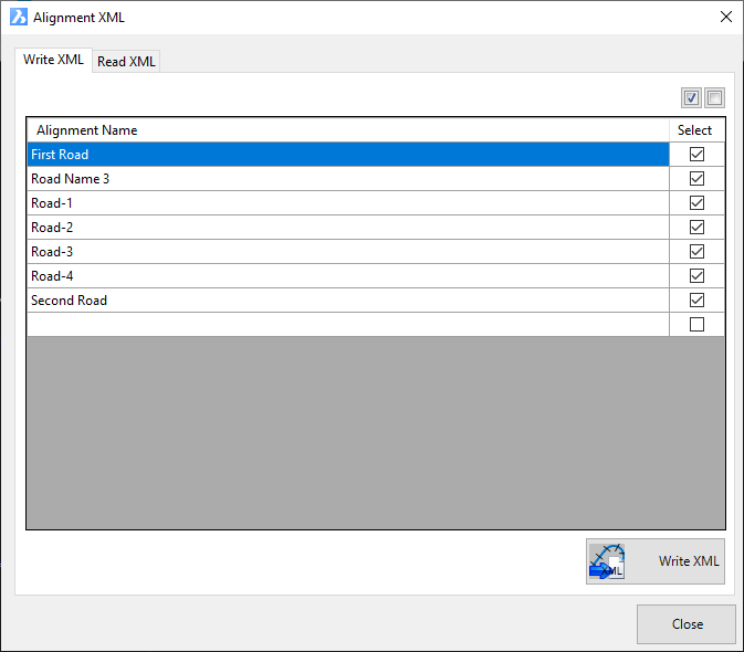
| Write XML |
Tab for exporting alignments to a Land XML file |
| |
|
 All On All On |
Ticks on all alignments in the list for export to a Land XML files |
 All Off All Off |
Unticks all alignments in the list for export to a Land XML files |
| Alignment Selection List |
Lists the alignments available for export to a LandXML file - items ticked on are set to be included in a LandXML file |
| Alignment |
Lists the alignments available for export. Non editable fields |
| Select |
Tick on/off alignments for inclusion in a LandXML file |
 Write XML Write XML |
Click to create a LandXML file containing the alignment data. A message box will display to confirm that the Land XML file has been created. By default, the exported file will by created in a folder named 'XMLExchangeFiles' located in the project data directory.
Note: By default, the Project Data Directory is located in the same folder as the current drawing, in a folder with the same name as the current drawing and with '-Data' added to the suffix |
|
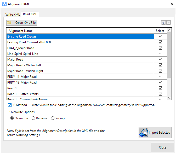
| Read XML |
Tab for importing alignments from a Land XML file into the software |
| |
|
 Open XML File Open XML File |
Click to select a Land XML file to open. Alignment data in the file will be presented in the Alignment Selection List. |
| All On |
Ticks on all alignments in the list for export to a Land XML files |
| All Off |
Unticks all alignments in the list for export to a Land XML files |
| Alignment Selection List |
Lists the alignments available for export to a LandXML file - items ticked on are set to be included in a LandXML file |
| Alignment |
Lists the alignments available for export. Non editable fields |
| Select |
Tick on/off alignments for inclusion in a LandXML file |
|
IP Method |
Tick on to enable IP editing of the imported alignments, subject to the geometry
supporting IP method creation and editing.
The following geometry is supported:
- tangent-tangent intersections
- tanget-curve-tangent combinations
- curve-curve combinations
- tangent-spiral-curve-spiral combinations
Note: When IP Method is selected, tangency will be applied for all
tangent-curve connections.
Where the IP Method cannot be applied, alignments will be imported as per the
XML geometry but without editing capabilities. Some element combinations
not supportive of the IP method includes:
- tangent-spiral-spiral-tangent combinations
- tangent-spiral-tangent combinations
- curves with direction change exceeding 180 degrees |
| Overwrite Options |
Where an alignment with the same name already exists in the project, the Overwrite Options sets how this conflict is to be resolved |
| Overwrite |
Replace all current alignments in the project with the alignment geometry from the Land XML file |
| Rename |
Rename the conflicting alignments and add them to the project |
| Prompt |
Prompt the user to select Overwrite or Rename whenever an alignment conflict is detected during the import. |
 Import
Selected Import
Selected |
Click to create a LandXML file containing the alignments
selected for import. A message box will display to confirm that the Land XML file has been created. By default, the exported file will by created in a folder named 'XMLExchangeFiles' located in the project data directory.
Note: By default, the Project Data Directory is located in the same folder as the current drawing, in a folder with the same name as the current drawing and with '-Data' added to the suffix |
|
| Close |
Close the form |
Add any notes about the output controls and any special conditions.